
Estimated Study Time: 9 minutes
Sizing batteries correctly
Batteries need to be sized correctly to be able to feed the required load for the required time, and a number of factors need to be decided to be able to optimize the battery for the duty expected. Some of these factors are fixed within the chemistry of each type of cell and, in some cases, the physical structure of the plates that make up the cell.
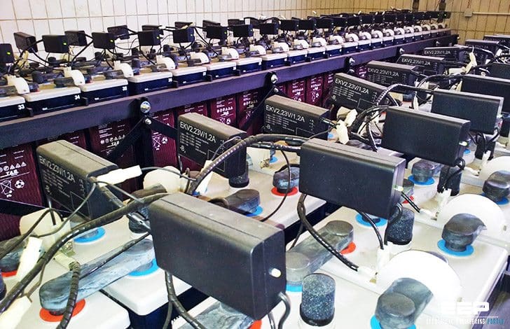 Three performance factors you must consider when sizing batteries (photo credit: Edvard CSANYI)
The performance is also influenced by the temperature and other location factors, and as an optimal combination of cells is needed to provide the required performance, the following important factors need to be considered:
System voltage (maximum and minimum)
The cells that make up any battery have a limited voltage range specific to the type of cell being used. In the case of lead acid batteries, the cell nominal voltage, which is the voltage of a fully charged cell without any input charge or load, is 2 V.
This is the float-charge voltage. Because individual cells in a battery can develop higher impedance than others when floated for a significant time, or after they are discharged, batteries only charged on “float” can result in some cells being less charged than others.
To overcome this condition, it is necessary to subject the battery to a higher voltage, the equalize charge voltage, which could be up to 2.7 V per cell.
Although the higher voltage would allow a faster recharge and would even up the charge on individual cells more quickly, this level of cell voltage would make the battery voltage range exceed the rating of most equipment that uses DC supplies.
It is therefore usual practice to keep the equalize charge in the range of 2.33 to 2.5 V per cell and extend the time required to equalize the battery.
Based on the above, the common battery size for a 125 V North American battery uses 60 cells with a battery voltage range of 105 to 140 V DC. This range is computed as follows:
- Equalizing voltage = 2.33 V per cell
- Maximum battery voltage under equalized charge = 60 V × 2.33 = 140 V
- Minimum volts per cell = 1.75 V
- Minimum battery voltage = 60 V × 1.75 = 105 V
Because the equipment fed by such a battery must also be operable with a level of voltage drop in the associated distribution cables, the operating range should cover the range 100–140 V. For international use, the typical lead acid battery consists of 55 cells having a battery voltage range of 96–128 V, resulting in a required equipment voltage range of 91–128 V.
Some earlier equipment, particularly the incandescent lights used for display indications, could not cover this range easily, and hence there is some use of batteries with a smaller number of cells and some use of end-cell switching when equalizing a battery.
It should be noted that, when using a smaller number of cells and a fixed minimum equipment operating voltage, the actual Ah rating needs to be increased to match the lower voltage range available unless the minimum equipment voltage rating can also be reduced.
The above examples are based on lead acid battery designs. For nickel cadmium and for other battery types, a similar series of voltage levels, and hence the number of cells used for a particular battery rating, can be established.
It should be also noted that the voltage range for the nickel cadmium battery system is larger than for the lead acid- based system, and hence precautions may need to be taken to protect sensitive equipment when nickel cadmium batteries are used.
However, for many modern digital systems, wide-range power units are used, and the large range of battery systems is less of a problem.
Go back to sizing batteries factors ↑
2. Correction factor
The capacity of all batteries changes with temperature, and for lead acid batteries, more change is found, particularly at the lower temperatures. The battery therefore has to be sized to provide the required standby time even under the worst applicable temperature conditions.
As each particular cell type has its own particular characteristics, the design curves for the particular cell type should be used in calculating the appropriate derating factor.
In new installations, the initial capacity is usually less than 100% (about 90%), and will only reach 100% after a few equalizing charges.
Industrial Batteries: The Dos and Don’ts
Go back to sizing batteries factors ↑
3. Duty cycle
It is necessary to detail the amount of power required for each function over the design discharge period. Typically, the various classes of load considered are as follows:
- Continuous load (indicating lamps, relays, etc.): 8 h
- Communications (UPS, etc.): 3 h
- Emergency light: 1⁄2–3 h
- Intermittent or momentary (CB close and trip): 1 min
General-purpose battery systems typically include both load types 1 and 4, as noted above, while the other types, particularly UPS, would be provided by dedicated batteries and require sufficient size to feed a fixed load level for a fixed time.
For mixed-use batteries, the loading with time and the method recommended to calculate the battery size required in power houses and switchyards is detailed in IEEE standards 485 [S1] and 1115 [S2], and are equally applicable to industrial situations.
The battery size given by each supplier depends on the minimum voltage at the end of the cycle which, for a lead acid battery with an 8-h standby time, should be not less than 1.75 V per cell.
Although actual switchgear operating times are short, the standards recommend using a 1-min value for a sum of the current taken by all devices simultaneously, with the circuit breakers tripping at the beginning and closing at the end (8 h) of the discharge cycle.
Go back to sizing batteries factors ↑
Reference // Industrial power systems by Khan Shoaib
Related electrical guides & articles


Edvard Csanyi
Hi, I'm an electrical engineer, programmer and founder of EEP - Electrical Engineering Portal. I worked twelve years at Schneider Electric in the position of technical support for low- and medium-voltage projects and the design of busbar trunking systems.I'm highly specialized in the design of LV/MV switchgear and low-voltage, high-power busbar trunking (<6300A) in substations, commercial buildings and industry facilities. I'm also a professional in AutoCAD programming.
Profile: Edvard Csanyi

It is very interesting information about battery and others.
thank you very much
Please send me the courses to me.
[email protected]
Thank you very much.
Referring to IEEE 485 battery sizing, if duty cycle diagrams are given in power (kW), with respect to time (min), normally it needs to be multiplied with battery capacity factors (mentioned as Ah/watt/cell) to calculate uncorrected Ah required for each section of load. Can anyone explain how that battery capacity factor is calculated for each use?
D-274 thermal power colony muzaffargarh
Very interesting articles!
Understanding Batteries are crucial for EV, ESS etc.
Please leave a link to ‘Save to PDF’ under the title.