
Estimated Study Time: 9 minutes
Case study
In this case study we describe a 13.8 kV switchgear phase-to-phase fault due to by heavy rain evolving into a three-phase fault that was cleared by transformer numerical relays. The generator was out of service and the fault was fed only from the 138 kV system.
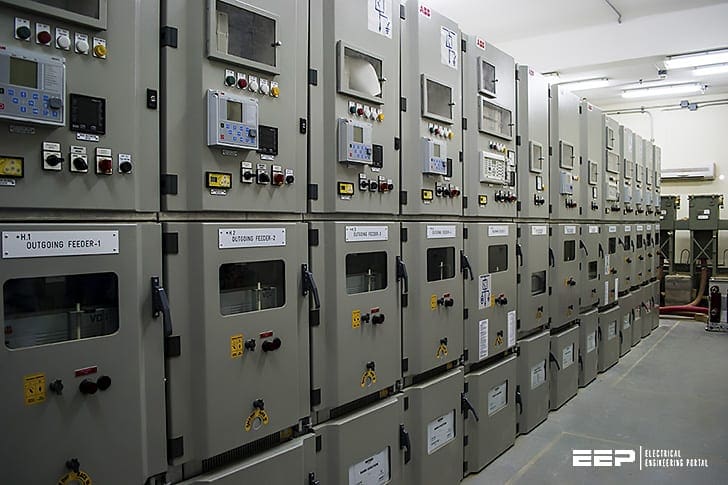 The case of phase-to-phase fault in a 13.8kV switchgear caused by heavy rain
We illustrate how a relay oscillography record for the 138-kV transformer side can be used to develop the analysis for the classification of the fault and confirmation of the fault location.
Since this study uses phase transformer differential relay 87TP, so let’s first remind of the basics of this protection.
Phase transformer differential relays 87TP
Description
The protective device provides restrained phase differential protection function with user-configurable multiple slope percentage restrained characteristic that allows to compensate both the static error and the dynamic error.
The static error accounts for transformer static magnetizing current and current measurement circuit calibration errors. The dynamic error may be caused by Tap Changing (OLTC) and by CT saturation caused by heavy fault currents.
In addition, the static tripping characteristic can be modified temporarily at the User’s choice to prevent some nuisance tripping from the harmonic inrush during energization, over-excitation, or deep CT saturation. The harmonic inrush is evaluated through 2nd, 4th harmonics and 5th harmonics transient is monitored through the CT saturation detector.
The phase differential protection can be used for this application scenario:
Related electrical guides & articles


Edvard Csanyi
Hi, I'm an electrical engineer, programmer and founder of EEP - Electrical Engineering Portal. I worked twelve years at Schneider Electric in the position of technical support for low- and medium-voltage projects and the design of busbar trunking systems.I'm highly specialized in the design of LV/MV switchgear and low-voltage, high-power busbar trunking (<6300A) in substations, commercial buildings and industry facilities. I'm also a professional in AutoCAD programming.
Profile: Edvard Csanyi
