
Estimated Study Time: 6 minutes
Distribution of AC power
AC power transmission is always at high voltage and mostly by 3-phase system. The use of single-phase system is limited to single-phase electric railways. Single-phase power transmission is used only for short distances and for relatively low voltages.
 Phases and wires in distribution of AC power
By the way, did you know that 3-phase power transmission requires less copper than either single-phase or 2-phase power transmission.
The distribution system begins either at the power substation where power is delivered by overhead transmission lines and stepped down by transformers or in some cases at the generating station itself. Where a large area is involved, primary and secondary distributions may be used.
With respect to phases, the six following systems are available for the distribution of AC power:
- Single-phase, 2-wire system
- Single-phase, 3-wire system
- Two-phase, 3-wire system
- Two-phase, 4-wire system
- Three-phase, 3-wire system
- Three-phase, 4-wire system
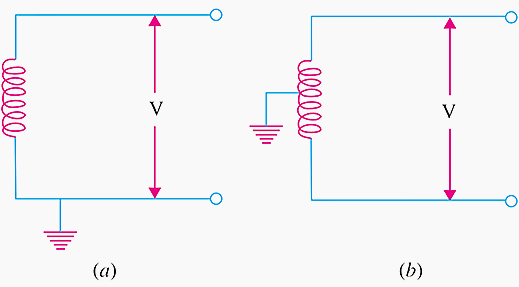
I. Single-phase, 2-wire System
It is shown in Figure 1 (a) and (b). In Figure 1 (a), one of the two wires is earthed whereas in Figure 1 (b) mid-point of the phase winding is earthed.
Go back to Distribution Systems ↑
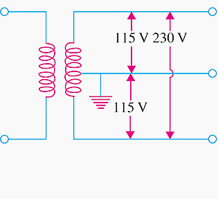
II. Single-phase, 3-wire System
The 1-phase, 3-wire system is identical in principle with the 3-wire DC system. As shown in Figure 2, the third wire or neutral is connected to the centre of the transformer secondary and earthed for protecting personnel from electric shock should the transformer insulation break down or the secondary main contact high voltage wire.
Go back to Distribution Systems ↑
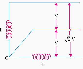
III. Two-phase, 3-wire System
This system is still used at some places. The third wire is taken from the junction of the two-phase windings I and II, whose voltages are in quadrature with each other as shown in Figure 3.
If the voltage between the third or neutral wire and either of the two wires is V, then the voltage between the outer wires is V as shown. As compared to 2-phase, 4-wire system, the 3-wire system suffers from the defect that it produces voltage unbalance because of the unsymmetrical voltage drop in the neutral.
Go back to Distribution Systems ↑
IV. Two-phase, 4-wire System
As shown in Figure 4, the four wires are taken from the ends of the two-phase windings and the mid-points of the windings are connected together.
As before, the voltage of the two windings are in quadrature with each other and the junction point may or may not be earthed. If voltage between the two wires of a phase winding be V , then the voltage between one wire of phase I and one wire of phase II is 0.707 V.

Go back to Distribution Systems ↑
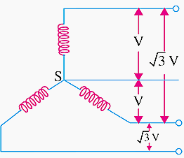
V. Three-phase, 3-wire system
Three-phase systems are used extensively. The 3-wire system may be delta-connected or star-connected whose star point is usually earthed.
The voltage between lines is V in delta-connection and √3 V in case of star connection where V is the voltage of each phase as shown in Figure 5 (a) and (b) respectively.

Go back to Distribution Systems ↑
VI. Three-phase, 4-wire system
The 4th or neutral wire is taken from the star point of the star-connection as shown in Figure 6 and is of half the cross-section of the outers or line conductors. If V is the voltage of each winding, then line voltage is 3 V. Usually, phase voltage i.e. voltage between any outer and the neutral for a symmetrical system is 230V so that the voltage between any two lines or outers is 3×230=400V.
Single-phase residential lighting loads or single-phase motors which run on 230 V are connected between the neutral and any one of the line wires. These loads are connected symmetrically so that line wires are loaded equally. Hence, the resultant current in the neutral wire is zero or at least minimum.
The three phase induction motors requiring higher voltages of 400 V or so are put across the lines directly.
Go back to Distribution Systems ↑
Three-phase tutorial – Currents in a delta //
Reference // Textbook of Electrical Technology – B.L. Theraja (Purchase from Amazon)
Related electrical guides & articles


Edvard Csanyi
Hi, I'm an electrical engineer, programmer and founder of EEP - Electrical Engineering Portal. I worked twelve years at Schneider Electric in the position of technical support for low- and medium-voltage projects and the design of busbar trunking systems.I'm highly specialized in the design of LV/MV switchgear and low-voltage, high-power busbar trunking (<6300A) in substations, commercial buildings and industry facilities. I'm also a professional in AutoCAD programming.
Profile: Edvard Csanyi

The technical details are very useful.
send information on this e-mail for now on —[email protected]
Transmission & distribution lines
In Israel are working 3 different one wire systems, see M. Bank, “It is Quite Another Electricity – Transmitting by one wire and without grounding”, Amazon. Com, 2016.system
It looks a technical impossibility
What hapens to phases currents of Feeder Transformer when there is a current returned by ground cable due wrong neutral x ground bondes on Site?
It looks a technical impossibility
I have some questions concerning the video “IRWIN 11.27 : Three Phase Tutorial; currents in a delta.”
1a). Should the star arm be [(24 +j18) / (cube root 3) = (13 +j10.35)] rather than (24 +j18) / 3 = (8 + j6) ?
b). The tutorial “Phases and wires in distribution of AC power” fig.5 shows [(V of Delta) = (cube root 3) * (V of Star)] configuration.
2. Should the [( Iba = (120 at angle 40 ) / ((0.5 +j0.4) +(8 + j6)) = (11.278 at angle 3.02 )A, rather than (18.3 at angle 3.02)A?
thanks Edvard, how about single phase 1 wire? (SWER) single phase high voltage (2 wire mainly but also substantial 1 wire) is very common in Australia, regards Mark