
Estimated Study Time: 14 minutes
Relay protection objectives
The objectives of the protection system are: to limit damage to people and to the plant, permit different service conditions, guarantee maximum service continuity for the plant not affected by faults and activate the automatisms provided. The protection relays are normally provided for different objectives and aims. In some cases a protection relay is used with the aim of activating automatisms to manage the electric network.
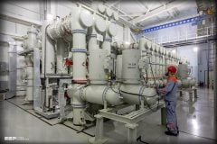
 Philosophy of a good relay protection settings for machines and plants (on photo: ABB's protecion relay REF542plus)
Protection settings & characteristics
The six most important characteristics of the protection system of an electric network are:
- Dependence: it can be called on to work after either a short or long period after installation. In any case, it must work when it is called on to operate;
- Safety: it must not operate when is not required (it must not operate during transients). It must allow the various service conditions and activate the automatisms provided;
- Selectivity: it must operate only and when necessary, guaranteeing maximum service continuity with minimum disconnection of the network;
- Speed: represented by the minimum fault time and by damage to the machinery;
- Simplicity: measured by the number of pieces of equipment needed to protect the network;
- Economy: assessed as the cost of the protection system in relation to the cost of malfunctioning.
The protection system is the ensemble of the instrument transformers and the relays with adequate settings. The relay is only one of the components making up the protection system.
Selection of the type of function and of the functions required to adequately protect a machine or a plant must be made on the basis of:
- Standards;
- Interface with the external network;
- Acceptable risk (consequences of the fault);
- Short-circuit currents (maximum and minimum);
- Status of the neutral;
- Presence of self-production in plant;
- Coordination with the existing system;
- Configurations and network running criteria;
- Practices.
The aim is to achieve the best technical-economic compromise which allows adequate protection against “faults” with “significant” probability and to verify that the investment is commensurate with the importance of the plant.
Protection types and applications
The electric protections are of different types and have different applications:
- Zone protections (e.g. differential or with impedance);
- Machine protections (e.g. reverse power);
- Selective protections (e.g. overcurrent);
- Non-selective protections (e.g. undervoltage, frequency);
- Protections in support (e.g. fuses, overcurrent, undervoltage);
- Interface protections (e.g. undervoltage protections; under/over and rate of change of frequency; overcurrent for disconnection between the plant network and the utility network);
- Protections for making automatisms (e.g. synchronism check).
The criterion which is followed when the setting of a protection is calculated is to efficaciously protect the machine or plant and then look for trip selectivity. Trip selectivity means isolating the smallest area of plant in the case of a fault in the shortest time possible (selectivity) and then to ensure a reserve (back-up) in the case of failure of the primary protection.
Selectivity criteria
There are various different selectivity criteria which can be used in plants:
- Time selectivity
- Current selectivity
- Differential protection and distance protection selectivity
- Logical selectivity
- Study of protection coordination
1. Time selectivity
Time type of selectivity is obtained by graduating the trip times of the protections (time discrimination or time selectivity) so that the relay closest to the fault trips in a shorter time compared to the ones further away.
This criterion has the serious disadvantage that the times for eliminating the fault cannot in any case be too long because:
- The materials do not support faults for long times;
- In the presence of a short-circuit there is a voltage drop (with, for example, consequent possible stoppage of low voltage loads due to de-excitation of the contactors);
- The longer the short-circuit remains supplied, the greater the damage created at the point of the fault is (with serious consequences as well, such as fires, etc.).

With regard to time graduation, this must take into account the characteristics of the apparatus present in the plant, and in the specific case of the medium voltage networks:
- Opening time of the medium voltage circuit breakers: ≈ 60 ms
- Inertia time of the protections: ≈ 20 ms
- Maximum timed trip error: ≈ 60 ms
- Safety margin: ≈ 50-100 ms
from which a graduation of about 200-250 ms between two protections in series is necessary
2. Current selectivity
Current type of selectivity is obtained by graduating the trip threshold of the protections to current values higher than those which can involve the load side protections (current discrimination or current selectivity). This can easily be made when an impedance of significant (typically a transformer or a reactance) is provided between two protections in series.
With this setting it is not necessary to introduce delay times between the two protections, and the supply side protection can be of instantaneous type since it only trips for faults in the part of plant included between the two protections.
3. Differential protection and distance protection selectivity
This kind of selectivity exploits the first law of Kirchoff at the node, i.e. the sum of the currents in a node must be equal to zero, if the summation of the currents is different from zero it means there is a fault.
With this criterion, the protection only identifies faults inside the component which is entrusted to it and consequently no selectivity control with other protections in the network is necessary and the trip can be of instantaneous type.
This selectivity criterion finds full application in high voltage as well, in setting the under-impedance (or distance) protections which only identify faults in the area of their competence.
4. Logical selectivity
Logical selectivity, also known as zone selectivity, is a selectivity criterion which was only introduced recently with the advent of digital protections. This selectivity criterion can be applied both to the overcurrent protections which identify phase faults, and to the overcurrent protections which identify gound faults.
The protection closest to the fault is not locked by any load side protection and consequently on expiry of its own trip time it commands opening of the switching part, isolating the fault selectively.

Logical type selectivity allows trip times to be reduced and full selectivity to be obtained in any case. The protections must be interconnected to allow the changeover of locks and consents (by means of pilot conductors and not by means of supervision systems which have incompatible response times) to allow correct operation. If the protections were not interconnected, there would be rapid tripping of all the protections run through by the fault current.
To guarantee correct operation of logical selectivity between the protections, it is necessary to introduce a short time delay to allow the protections the correct changeover (sending and/ or acquisition) of the locking signals.
In general, when logical selectivity is active, other overcurrent, phase and ground thresholds not subject to logical locks are also provided in back-up.
5. Study of protection coordination
Installing protections in a network and not setting them suitably is the same as not installing the protection system. The protection system is really only such if the protection functions necessary are provided and these are suitably set.
The protection coordination study basically consists of setting tables for the protections and selectivity diagrams (in bilogarithmic scale) where what the trip sequence of the network protections is highlighted for each current value which involves the circuit.
To work out a correct protection coordination study, some fundamental factors must be taken into account, such as:
FACTOR #1 – The study must be based on the short-circuit currents. It must be remembered that the protection is inserted in a circuit and therefore the current which it can measure is only the one which passes through that circuit (it can be also be much lower than the short-circuit overcurrent of the switchgear the circuit is connected to).
FACTOR #2 – For ground protections with isolated neutral or grounded by means of a limiting impedance, an independent selectivity diagram must be provided for phase or ground protections.
FACTOR #3 – The tolerability of the various components of the plant must be indicated in the selectivity diagrams to check that they are adequately protected. For example, the withstand of the transformers or of the cables.
FACTOR #4 – Where particular service criteria of the plant require it, it is necessary for the trip curves of the voltage relay to be given as well in the selectivity diagrams to demonstrate trip selectivity between current and voltage protections.
FACTOR #5 – For the direct low voltage protections the trip curves corresponding to the operating times of the protection are given in the selectivity diagrams, which coincide with the circuit breaker times.
For medium or high voltage protections (therefore for indirect relays) the relay trip curves are generally given in the coordination diagrams to which the circuit-breaker operating time is obviously added in order to obtain the total time for eliminating the fault, so the two families of curves are not homogeneous.
Particular attention must paid in the protection coordination study to verifying that the protections do not cause unwanted trips. The latter are, in fact, often more devastating than a normal trip of the protections since, not finding faults in the network the operator does not know how and within what time to resume service.
Reference // Protection criteria for MV networks by ABB
Related electrical guides & articles


Edvard Csanyi
Hi, I'm an electrical engineer, programmer and founder of EEP - Electrical Engineering Portal. I worked twelve years at Schneider Electric in the position of technical support for low- and medium-voltage projects and the design of busbar trunking systems.I'm highly specialized in the design of LV/MV switchgear and low-voltage, high-power busbar trunking (<6300A) in substations, commercial buildings and industry facilities. I'm also a professional in AutoCAD programming.
Profile: Edvard Csanyi

What are step calculation of relay protection?
I’m surprised and happy to get useful information.
Very nice information thank you for that and I just request you please share information about “harmonic current”.
thank you
Thank you, it’s very nice and informative article for freshest and even the experienced to understand the concept in better way.
I am a retired electrical engineer,from CHENNAI, INDIA. Specialized in EHV Substations,including design,installation and commissioning. I find the subject article extremely lnformatove and interesting. Thanks.
Only experts can analyse like this.
Nice information
Excellent summary to Protection Systems
Edvard, I like to express my gratitute and thanks to these educative materials that you post. they are very enlightening.
once again I would like to say a big Thank you
Excellent summary of Introduction to Protection Systems. Congratulations.
Best regards.
Hi edvard
We can add an arc flash protection relay from vamp or siemens or…in the aim to limit the current fault impact…it is based on lighting analog sensors to provide a quick response
In fact in sole cases there is some delays caused by the logical selectivity
Regards
Ali
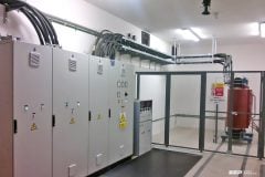
Philosophy of a good protection settings for machines and plants
Excellent!
best regards