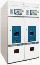
The PIX metal-clad switchboards are extensible on both sides and consist of modular functional units, linked by a busbar, and connected to the substation earth via an earthing bus.
The cubicles are subdivided by metal partitions into four separate compartments, including a low voltage compartment for the control and monitoring equipment.
The three Medium Voltage compartments; bus bar, equipment & cables, are fitted with an overpressure release system, oriented towards the top of the unit inside of cubicle volume. The fused switch-disconnectors are fixed type in the compartimented unit.
Main module compartment
Closed off by a door, this compartment contains:

A withdrawable module, fitted with a circuit breaker or contactor, which has two positions, “plugged in” or “disconnected/test”. All operations of the withdrawable module and its associated equipment can be carried out with the compartment door closed. For modules fitted with vacuum circuit breakers, the movement can be motorised.
Withdrawable modules of the same type are interchangeable. The connection between the withdrawable module, the busbar and the cable branches is made by means of withdrawable silver plated contacts. A 64-pin plug (Max.) connects the auxiliary circuits of the withdrawable module to the low voltage compartment.
For personnel safety, there are metallic shutters, installed in front of the spouts of the fixed “plug-in” contacts, which prevent access to the primary circuit, thus ensuring a protection when the withdrawable module is either in the “disconnected/test” position or removed from the compartment. Once the withdrawable module has been removed, each shutter can be padlocked individually. With the interlocking shutters option, the independant opening of the upper or lower shutter is only possible using a special tool (optionally supplied).
An earthing device for the removable module, to the IEC standards, ensures earthing continuity during removal, either through rullers or through an optional plug. An inspection window on the door, allows the position of the withdrawable module to be clearly seen within the compartment. Its position is also shown on the mimic diagram on the DCX control unit.
The PIX system also offers, amongst the range of withdrawable modules, the functions of disconnecting link, voltage transformers and busbar earthing switch. This compartment is fitted with mechanical locking devices in accordance with IEC standards, which are necessary to avoid any unsafe operations.
Cable compartment

Normally closed with a bolted panel, accessible from the front panel, and with a removable horizontal panel between the cable & main module compartment, this design is made for ease of assembly and on-site testing of cables and accessories.
As an option, and depending on the installation of switchboard chosen, the rear panel can be made removable, to further improve access.
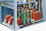
This compartment contains:
- The connections to the power cables, up to 6 x 630 mm02 per phase, with a choice of bottom plate.
- The cable earthing switch is operated from the front of the cubicle by means of a removable lever. Its position is visible from the front panel, through the inspection window in the cable panel.
- Current transformers, with DIN dimensions, are fitted at the rear of the cubicle.
- The voltage transformers, fitted at the front of the compartment, are either fixed – with or without fuses, or removable with fuses.
- A metallic cable duct, located on the right-hand lateral part, guides the low voltage conductors into the control/command compartment safely.
At the front, upper section of this compartment, is the access to the earthing switch controls, along with its mimic diagram and VPIS type voltage indicators (IEC 61958). VDS type voltage indicators (IEC 612345) can be offered as an option.
Busbar compartment

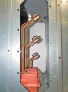
Busbar compartment is located in the upper, rear of the unit, this compartment is accessible via the top or front panel of the cubicle, after removing the partitions, which separate it from the switchgear compartment.
The bus bar consists of flat copper with rounded edges. The rated current will determine the number of bars to be mounted in parallel. The bus bar is linked and supported by solid connections to the spouts.
Optionally, this compartment can be fitted with:
- Segregations made of insulating materials, resistant to pressure, mounted between each cubicle.
- Encapsulation of the bus bars and branch connections.
- Fixed voltage transformers, without fuses.
- An earthing switch.
Low voltage compartment

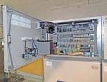
This compartment contains all the secondary circuit functions for control, measurement, protection, monitoring, communication and other associated systems.
This independent compartment, is a separate assembly, supplied fully assembled and tested.


Current Rating in busbar and current rating in Circuit breaker is different, Could you explain me why the difference
May I,get information abaut PIX (Vaccum version) Schneider in pdf?and may EEP have IEC 62271-100 and iec 62271-200,can shared with me?thaks and warm regrad
is the VCB tested inside the panel and what is the type that has been types tested?
Customer choice of Low Voltage Switch gears are obtainable in nearest place.
PIX24 is medium voltage switchgear, not low voltage.
Of course! PIX 24 comply standard IEC 62271-200 (Switchgear).
Here is the full list of all regulations, provisions and standards that PIX 24 comply:
– Switchgear: IEC 62271-200 / EN 62271-200
– Internal arc qualification: IEC 62271-200 / EN 62271-200
– Earthing switch/disconnector: IEC 62271-102 / EN 62271-102
– Fuse switch-disconnector combination: IEC 60265-1 / EN 60265-1
– Circuit breaker: IEC 62271-105 / EN 62271-105
– Vacuum contactor: IEC 62271-100 / EN 62271-100
– Current transformer: IEC 60470 / EN 60470
– Voltage transformer: IEC 60044-1 / EN 60044-1
– Voltage Detecting Systems (VDS): IEC 60044-2 / EN 60044-2
– Protection against accidental contact: IEC 61243-5
– Foreign bodies and water: IEC 60529 / EN 60529
– Erection: HD 637 S1
– Operation of electrical equipment: EN 50110-1
– Environment and operating conditions: IEC 60694 / EN 60694 (in future IEC 62271-1)
More info on Standard 62271-200 you can find here:
https://electrical-engineering-portal.com/iec-62271-200
BR
It is very useful to know how to use switch gear and bus bar.
Thank you very much! Soon there will be another yet relayed article ‘MiCOM – Advanced protection and control relay’ also from Ex Areva, now Schneider Electric manufacturer.
BR
I’m looking for MV switchgear can meet 31.5kA Internal Arc Withstand as per IEC 62271-200. Any brand can comply and completed with type test certificate? Is the AREVA PIX fully type test for internal arc as per IEC 62271-200?
Yes, PIX have type test per IEC62271-200 for internal arc protection up to 40kA.
Get in direct contact with me through Schneider-Electric Serbia to get a copy of type test.