
Estimated Study Time: 7 minutes
Planning high voltage switchgear
The following three criteria must be considered when planning high voltage switchgear installations:
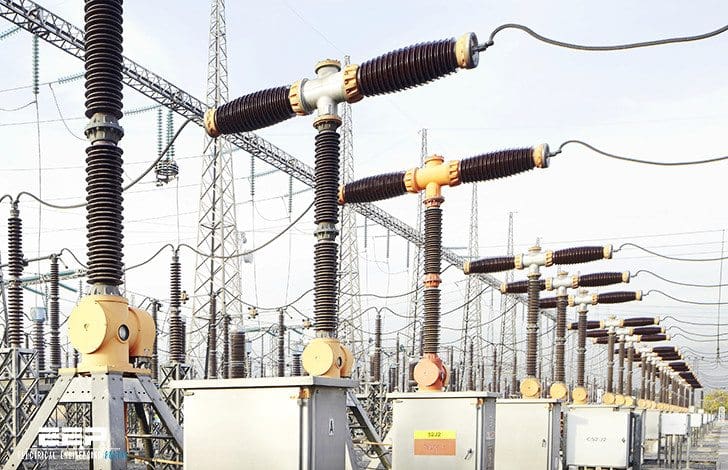 Consider this when planning high voltage switchgear installations (photo credit: ABB)
1. Voltage levels
High voltage installations are primarily for power transmission, but they are also used for distribution and for coupling power supplies in three-phase and HVDC systems. Factors determining their use include: network configuration, voltage, power, distance, environmental considerations and type of consumer:
| HV Installations | Voltage level |
| Distribution and urban networks | > 52 – 245 kV |
| Industrial centres | > 52 – 245 kV |
| Power plants and transformer stations | > 52 – 800 kV |
| Transmission and grid networks | 245 – 800 kV |
| HVDC transmission and system interties | > 300 kV |
| Railway substations | 123 – 245 kV |
2. Plant concept and configuration
The circuitry of an installation is specified in the single-phase block diagram as the basis for all further planning stages. Table 1 shows the advantages and disadvantages of some major station concepts.
The availability of a switching station is determined mainly by:
- Circuit configuration, i. e. the number of possibilities of linking the network nodes via circuit breakers and isolators, in other words the amount of current path redundancy,
- Reliability/failure rate of the principal components such as circuit breakers, isolators and busbars,
- Maintenance intervals and repair times for the principal components.
Table 1 – Choice of plant concept and measures taken in relation to given boundary conditions
| Concept configuration | Advantages | Disadvantages |
| Single busbar |
|
|
| Single busbar with bypass |
|
|
| Double busbar with one circuit breaker per branch |
|
|
| 2-breaker system |
|
|
| Ring bus |
|
|
| 1½-breaker system |
|
|
3. Dimensioning
On the basis of the selected voltage level and station concept, the distribution of power and current is checked and the currents occurring in the various parts of the station under normal and short-circuit conditions are determined.
The basis for dimensioning the station and its components is defined in respect of:
- insulation coordination
- clearances, safety measures
- protection scheme
- thermal and mechanical stresses
The basic designs available for switching stations and equipment together with different forms of construction offer a wide range of possibilities, see Table 2 below. The choice depends on environmental conditions and also constructional, operational and economic considerations.
Table 2 – The principal types of design for high voltage switchgear installations and their location
| Basic design | Insulation medium | Used mainly for voltage level (kV) | Location | |
| Outdoor | Indoor | |||
| Conventional | Air | >52 – 123 | × | × |
| Conventional | Air | 123 – 800 | × | |
| GIS | SF6 | >52 – 800 | × (1) | × |
| Hybrid (2) | Air/SF6 | 245 – 500 | × | |
- GIS used outdoors in special cases
- Hybrid principle offers economical solutions for station conversion, expansion or upgrading.
There are various layouts for optimizing the operation and space use of conventional outdoor switchgear installations (switchyards), with different arrangement schemes of busbars and disconnectors.
North-East Agra – the world’s first multi-terminal UHVDC transmission link
The 800 kV North-East Agra UHVDC (ultra high voltage direct current) link will have a record 8,000 MW converter capacity, transmitting clean hydroelectric power, equivalent to the generation of 8 large power plants, from India’s northeast region to the city of Agra, a distance of 1,728 km.
The North-East Agra project was ABB’s fifth HVDC transmission link in India at that time.
Reference // Switchgear manual by ABB (Order PDF or hardcover directly from ABB)
Related electrical guides & articles


Edvard Csanyi
Hi, I'm an electrical engineer, programmer and founder of EEP - Electrical Engineering Portal. I worked twelve years at Schneider Electric in the position of technical support for low- and medium-voltage projects and the design of busbar trunking systems.I'm highly specialized in the design of LV/MV switchgear and low-voltage, high-power busbar trunking (<6300A) in substations, commercial buildings and industry facilities. I'm also a professional in AutoCAD programming.
Profile: Edvard Csanyi
