Reduced-voltage-start motor control circuit
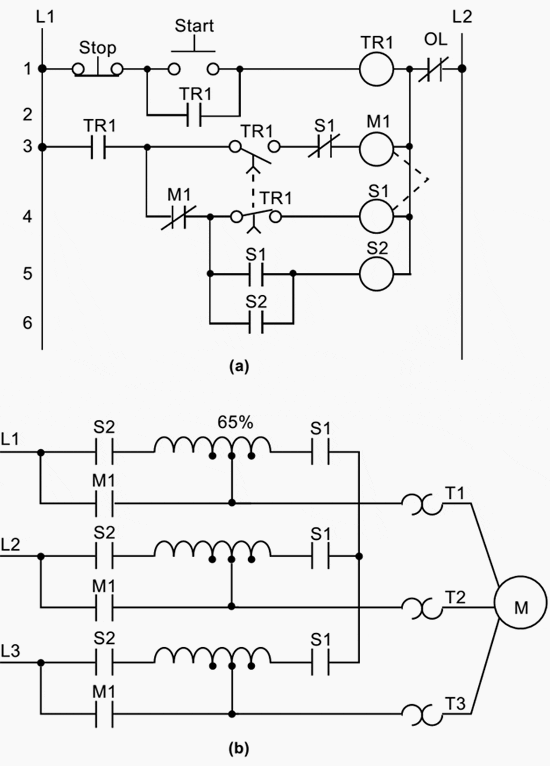
Figure 1 shown below illustrates the control circuit and wiring diagram of a 65% tapped, autotransformer, reduced-voltage-start motor control circuit. This reduced voltage start minimizes the inrush current at the start of the motor (locked rotor current) to 42% of that at full speed.

In this example, the timer must be set to 5.3 seconds. Also, the instantaneous contacts from the timer in lines 2 and 3 must be trapped.

Hardwired circuit (real I/O)
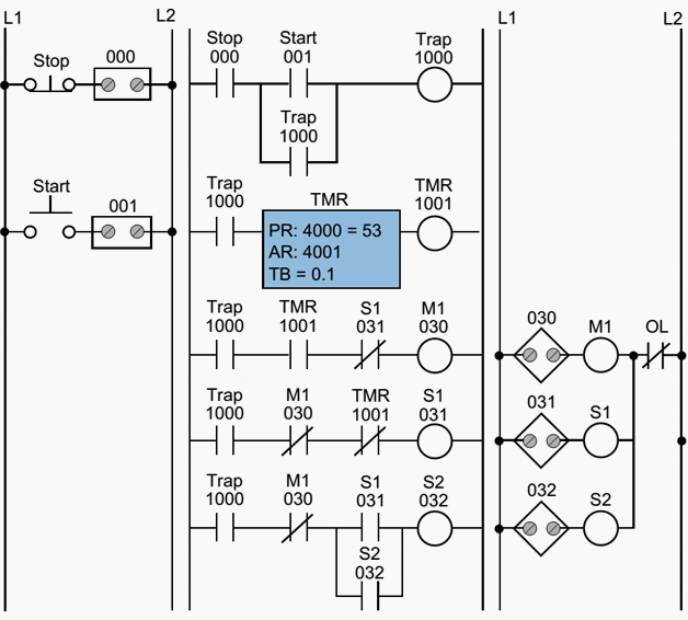
Figure 2 illustrates the hardwired circuit with the real inputs and outputs circled. The devices that are not circled are implemented inside the PLC through the programming of internal instructions.

Tables 1, 2, and 3 show the I/O assignment, internal assignment, and register assignment, respectively.
Figure 3 illustrates the PLC implementation of the reduced-voltage start circuit. The first line of the PLC program traps the timer with internal output 1000. Contacts from this internal replace the instantaneous timer contacts specified in the hardwired control circuit. This PLC circuit implementation does not provide low-voltage protection, since the interlocking does not use the physical inputs of M1, S1, and S2.
Table 1 – I/O address assignment
| I/O Address | ||||
| Module Type | Rack | Group | Terminal | Description |
| Input | 0 | 0 | 0 | Stop PB (NC) |
| 0 | 0 | 1 | Stop PB (NO) | |
| Output | 0 | 3 | 0 | Motor Starter M1 |
| 0 | 3 | 1 | S1 | |
| 0 | 3 | 2 | S2 | |
Table 2 – Internal address assignment
| Device | Internal | Decription |
| — | 1000 | Trap Timer Circuit |
| Timer | 1001 | Timer |
Table 3 – Register assignment
| Register | Decription |
| 4000 | Preset register value 53, time base 0.1 sec. for 5.3 sec. (timer output is 1001) |
| 4001 | Accumulated register for timer output 1001 |

If the auxiliary contacts or the overloads are used as inputs, they must be programmed as normally open (closed when the overloads are closed and the motor is running) and placed in series with contact 1000 in line 3 of the PLC program. If the overloads open, the circuit will lose continuity and M1 will turn OFF.
Resource: Introduction-to-PLC-Programming – www.globalautomation.info


TR1 is a timer relay.
You’ve mentioned that,at the time of PLC programming, one should consider OL as NO contact. I think it should be “examine if open” (XIO) or NC contact. If not,how could you start the motor without energising the OL !
The picture is a horror, it is real bad practice and the comments are given in plcs.net for long time.
the timer should be set to the needed time to have the motor running at normal speed.
this can be from 2 to 30 seconds.
hardware circuit is correct
i/o address assignment line 2 should be start button
in program the O/L should be detected, when resetted the motor will have full power as M1 is still active thus the coil M1 (please use different names internal and external) will be activated.
greetings [email protected]