
Estimated Study Time: 7 minutes
AC Motor Drive Interface
A common PLC application is the speed control of AC motors with variable speed (VS) drives. The diagram in Figure 1 shows an operator station used to manually control a VS drive.
The programmable controller implementation of this station will provide automatic motor speed control through an analog interface by varying the analog output voltage (0 to 10 VDC) to the drive.
The operator station consists of:
- a speed potentiometer (speed regulator),
- a forward/reverse direction selector,
- a run/jog switch, and
- start and stop push buttons.
The PLC program will contain all of these inputs except the potentiometer, which will be replaced by an analog output.
The PLC program will contain the logic to start, stop, and interlock the forward/reverse commands.

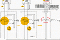
Table 1 shows the I/O address assignment table for this example, while Figure 2 illustrates the connection diagram from the PLC to the VS drive’s terminal block (TB-1). The connection uses a contact output interface to switch the forward/reverse signal, since the common must be switched.
To activate the drive, terminal TB-1-6 must receive 115 VAC to turn ON the internal relay CR1. The drive terminal block TB-1-8 supplies power to the PLC’s L1 connection to turn the drive ON. The output of the module (CR1) is connected to terminal TB-1-6. The drive’s 115 VAC signal is used to control the motor speed so that the signal is in the same circuit as the drive, avoiding the possibility of having different commons (L2) in the drive (the start/stop common is not the same as the controller’s common).
In this configuration, the motor’s overload contacts are wired to terminals TB-1-9 and TB-1-10, which are the drive’s power (L1) connection and the output interface’s L1 connection. If an overload occurs, the drive will turn OFF because the drive’s CR1 contact will not receive power from the output module.
To have low-voltage protection, the auxiliary contact from the drive, CR1 in terminal TB-1-7, must be used as an input in the PLC, so that it seals the start/stop circuit.


Figure 3 shows the PLC ladder program that will replace the manual operator station. The forward and reverse inputs are interlocked, so only one of them can be ON at any given time (i.e., they are mutually exclusive).
If the jog setting is selected, the motor will run at the speed set by the analog output when the start push button is depressed. The analog output connection simply allows the output to be enabled when the drive starts. Register 4000 holds the value in counts for the analog output to the drive. Internal 1000, which is used in the block transfer, indicates the completion of the instruction.
Sometimes, a VS drive requires the ability to run under automatic or manual control (AUTO/MAN). Several additional hardwired connections must be made to implement this dual control.

Note that the start, stop, run/jog, potentiometer, and forward/reverse field devices shown are from the operator station. These devices are connected to the PLC interface under the same names that are used in the control program (refer to Figure 3).
If the AUTO/MAN switch is set to automatic, the PLC will control the drive; if the switch is set to manual, the manual station will control the drive.

Resource: Introduction-to-PLC-Programming – www.globalautomation.info
Related electrical guides & articles


Edvard Csanyi
Hi, I'm an electrical engineer, programmer and founder of EEP - Electrical Engineering Portal. I worked twelve years at Schneider Electric in the position of technical support for low- and medium-voltage projects and the design of busbar trunking systems.I'm highly specialized in the design of LV/MV switchgear and low-voltage, high-power busbar trunking (<6300A) in substations, commercial buildings and industry facilities. I'm also a professional in AutoCAD programming.
Profile: Edvard Csanyi

Hi please could you kindly upload video’s from basic wiring to programming vsds and plc basic to in-depth I’m a beginner in the field any help will be useful thank you
can you please help me on how to use analog output from the plc to a drive a Speed drive?
Hello Please I’m Woking On Powerflex 4m variable frequency drive and i want to control the speed through my PLC
dear sir,
I am using yaskawa F7 varispeed drive with start command & speed for potentiometer for speed reference.Now I want to run my drive in 2steps.
1step-start with normal/minimum frequency
2step-after giving 2nd command run with maximum frequency
and after withdrawing 2nd command run in normal/minimum freq. or vise-versa
Excellent work Edvard.. praiseworthy efforts
EXCELENTE DOCUMENTO PARA UN INICIO DE DESARROLLO DE SOLUCIONES INTEGRANDO PLCs Y VARIADORES DE FRECUENCIA. YO TRABAJO CON MITSUBISHI UTLIZANDO GX WORKS 2 PARA PROGRAMACION, ESTE TIENE INSTRUCCIONES DEDICADAS PARA VARIADORES IGUAL QUE TODOS LOS SOFTWARES DE ULTIMA GENERACIONES LOS CUALES TIENEN UN GRAN VALOR AGREGADO ADEMAS DE CUMPLIR LA NORMA DE SOFTWRAES DE PLC.GRACIAS.
How I can download software of PLC??
I can’t find it..
Hello sir, I want to learn analog programming in plc, but I can’t find enough stuff at Google or elsewhere , please guide…
Hi Edvard, Thank you for the article, helped me, but I still got a question for you:
In Figure 3 (ladder diagram it self) a contact “STOP” PB2 001 normally open, shouldn’t it be normally closed?
Thank you,
svinder
thank you