Forward/Reverse Motor Interlocking
Figure 1 illustrates a hardwired forward/reverse motor circuit with electrical and push button interlockings.
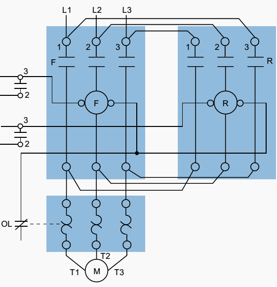
Figure 2 shows the simplified wiring diagram for this motor. The PLC implementation of this circuit should include the use of the overload contacts to monitor the occurrence of an overload condition.
The auxiliary starter contacts (M1 and M2) are not required in the PLC program because the sealing circuits can be programmed using the internal contacts from the motor outputs.
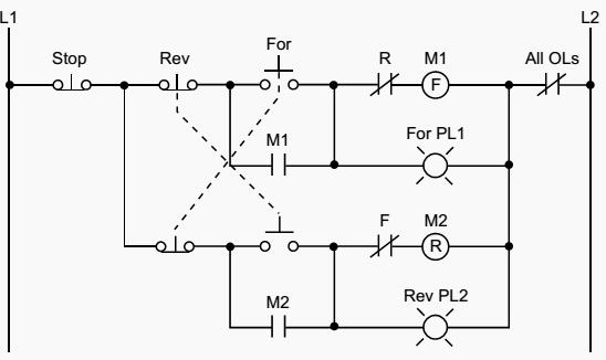
Low-voltage protection can be implemented using the overload contact input so that, if an overload occurs, the motor circuit will turn off. However, after the overload condition passes, the operator must push the forward or reverse push button again to restart the motor.
For simplicity, the PLC implementation of the circuit in Figure 1 includes all of the elements in the hardwired diagram, even though the additional starter contacts (normally closed R and F in the hardwired circuit) are not required, since the push button interlocking accomplishes the same task.
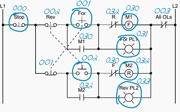
Figure 3 shows the field devices that will be connected to the PLC. The stop push button has address 000, while the normally open sides of the forward and reverse push buttons have addresses 001 and 002, respectively. The overload contacts are connected to the input module at address 003.
Additionally, the overload light indicators have addresses 034 and 035, indicating that the overload condition occurred during either forward or reverse motor operation. The addresses for the auxiliary contact interlocking using the R and F contacts are the output addresses of the forward and reverse starters (030 and 032). The ladder circuit that latches the overload condition (forward or reverse) must be programmed before the circuits that drive the forward and reverse starters as we will explain shortly. Otherwise, the PLC program will never recognize the overload signal because the starter will be turned off in the circuit during the same scan when the overload occurs.
If the latching circuit is after the motor starter circuit, the latch will never occur because the starter contacts will be open and continuity will not exist.
Table 1 shows the real I/O address assignment for this circuit. Figure 4 shows the PLC implementation, which follows the same logic as the hardwired circuit and adds additional overload contact interlockings.
Table 1 – I/O address assignment
| I/O Address | ||||
| Module Type | Rack | Group | Terminal | Description |
| Input | 0 | 0 | 0 | Stop PB (wired NC) |
| 0 | 0 | 1 | Fowrward PB (wired NO) | |
| 0 | 0 | 2 | Reverse PB (wired NO) | |
| 0 | 0 | 3 | Overload contacts | |
| Input | 0 | 0 | 4 | Acknowledge OL/Reset PB |
| – | – | – | ||
| – | – | – | ||
| – | – | – | ||
| Output | 0 | 3 | 0 | Motor starter M1 (FWD) |
| 0 | 3 | 1 | Forward PL1 | |
| 0 | 3 | 2 | Motor starter M2 (REV) | |
| 0 | 3 | 3 | Reverse PL2 | |
| Output | 0 | 3 | 4 | Overload condition FWD |
| 0 | 3 | 5 | Overload condition REV | |
| 0 | 3 | 6 | – | |
| 0 | 3 | 7 | – | |
Note that the motor circuit also uses the overload input, which will shut down the motor. The normally closed overload contacts are programmed as normally open in the logic driving the motor starter outputs. The forward and reverse motor commands will operate normally if no overload condition exists because the overload contacts will provide continuity.
However, if an overload occurs, the contacts in the PLC program will open and the motor circuit will turn OFF. The overload indicator pilot lights (OL Fault Fwd and OL Fault Rev) use latch/unlatch instructions to latch whether the overload occurred in the forward or reverse operation.
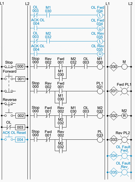
Again, the latching occurs before the forward and reverse motor starter circuits, which will turn off due to the overload. An additional normally open acknowledge overload reset push button, which is connected to the input module, allows the operator to reset the overload indicators. Thus, the overload indicators will remain latched, even if the physical overloads cool off and return to their normally closed states, until the operator acknowledges the condition and resets it.
Figure 5 illustrates the motor wiring diagram of the forward/reverse motor circuit and the output connections from the PLC. Note that the auxiliary contacts M1 and M2 are not connected.
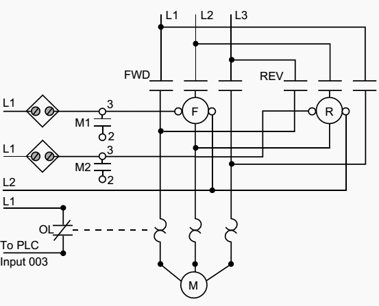
In this wiring diagram, both the forward and reverse coils have their returns connected to L2 and not to the overload contacts. The overload contacts are connected to L1 on one side and to the PLC’s input module on the other (input 003). In the event of an overload, both motor starter output coils will be dropped from the circuit because the PLC’s output to both starters will be OFF.
Control circuit for forward and reverse motor (VIDEO)
Cant see this video? Click here to watch it on Youtube.
Reference: Resource: Introduction-to-PLC-Programming – www.globalautomation.info


i want to learn PLC Programming and Auto cat 3D
sir i need about plc.how it make a ladder diagram and how it works
sir i need to know the applications for reverse and forward control and power circuits
NEED HELP WITH PROJECT…..
how can i run NEMA 23 stepper motor from 230V?
criterias – the motor should move forward for certain RPMs at low speed then stop.and after supply cut off it should move revese exact sam rpm & exact same speed?
Is it a good idea to use the auxiliary of the motor starter as a “real” seal-in, so that in the event of a power loss the motor will drop out? A fictional bit will automatically cause a restart.
sir i want basic techniques of plc to get soon…what can i do..because i m also the student of MSC Electronics Enginnering.
what is inching in case of electricmotor
Dear Edward
I am one of the regular reader of your articles. You are doing awesome job here.
Thank you very much for this article. This is very informative for me and hope fully for others also.
Reaally really useful for my professional life. Hats off sir… Really a great job….
Great stuff. Keep the articles rolling
There was no PLC at the time I learned this schematic (1993) during my vocational school class. After the simple diagram start-stop of a motor , the teacher decide for F-R implementation to give as 30 minutes to conceive this schematic. i am very grateful for all the effort. Keep up with the great work.
I am very thankful with your information.
It is very useful to me thank you
Nice to see the PLC code originating in a hardwired circuit.
We have forgotten that it all started there.
Nice to learn