
Estimated Study Time: 3 minutes
Detection of position
In this example (see Figure 1), we will implement a control program that detects the position of a bottle via a limit switch, waits 0.5 seconds, and then fills the bottle until a photosensor detects a filled condition.

After the bottle is filled, the control program will wait 0.7 seconds before moving to the next bottle. The program will include start and stop circuits for the outfeed motor and the start of the process. Table 1 shows the I/O address assignment, while Tables 2 and 3 present the internal and register assignments, respectively.
These assignments include the start and stop process signals.
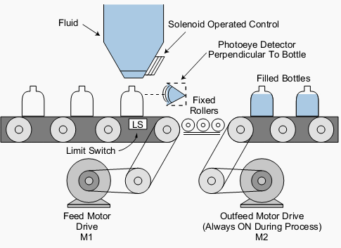
Table 1 – I/O address assignment
| I/O Address | ||||
| Module Type | Rack | Group | Terminal | Description |
| Input | 0 | 0 | 0 | Start process PB1 |
| 0 | 0 | 1 | Stop process PB2 (NC) | |
| 0 | 0 | 2 | Limit switch (position detect) | |
| 0 | 0 | 3 | Photoeye (level detect) | |
| Output | 0 | 3 | 0 | Feed motor M1 |
| 0 | 3 | 1 | Outfeed motor M2 (system ON) | |
| 0 | 3 | 2 | Solenoid control | |
| 0 | 3 | 3 | — | |
Table 2 – Internal output assignment
| Device | Internal | Description |
| Timer | 1001 | Timer for 0.5 sec delay after position detect |
| Timer | 1002 | Timer for 0.7 sec delay after level detect |
| — | 1003 | Bottle filled, timed out, feed motor M1 |
Table 3 – Register assignment
| Register | Description |
| 4000 | Preset value 5, time base 0.1 sec (1001) |
| 4001 | Accumulated value for 1001 |
| 4002 | Preset value 7, time base 0.1 sec (1002) |
| 4003 | Accumulated value for 1002 |
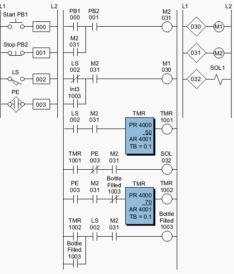
Figure 2 illustrates the PLC ladder implementation of the bottle-filling application. Once the start push button is pushed, the outfeed motor (output 031) will turn ON until the stop push button is pushed.
The feed motor M1 will be energized once the system starts (M2 ON); it will stop when the limit switch detects a correct bottle position. When the bottle is in position and 0.5 seconds have elapsed, the solenoid (032) will open the filling valve and remain ON until the photoeye (PE) detects a proper level.
The bottle will remain in position for 0.7 seconds, then the energized internal 1003 will start the feed motor. The feed motor will remain ON until the limit switch detects another bottle.
Reference: Introduction to PLC Programming and Implementation – from relay logic to PLC logic – globalautomation.info
Related electrical guides & articles


Edvard Csanyi
Hi, I'm an electrical engineer, programmer and founder of EEP - Electrical Engineering Portal. I worked twelve years at Schneider Electric in the position of technical support for low- and medium-voltage projects and the design of busbar trunking systems.I'm highly specialized in the design of LV/MV switchgear and low-voltage, high-power busbar trunking (<6300A) in substations, commercial buildings and industry facilities. I'm also a professional in AutoCAD programming.
Profile: Edvard Csanyi

Üdv Edvárd!
Úgy örülök, hogy megtaláltam ezt az oldalt.
Dear Edvard!
I am glad to find this website. I am a teacher in Hungary and I have become infected with automation in Taiwan, so I am 47 and I now start to study this beautiful part of electrical engineering.
Steyer Zalán
I maintain a water bottling facility using krones equipment a German manufacturer plant is based in the US experiencing malfunction that could be attributed to discrepancies between NEC wiring methods and European ones could shed some light on the subject.
Nice Explained
thanks for these refreshments education i value them.
Ver useful site
Thank you verymuch
why ls002 in last line ?
i like this website very much.thank u
Im having trouble programming my project for collage. It is a pick and place arm using two stepper motors, im using a mitsubishi FX 1s 30mt transistor output but I cant seem to get it to work. Im not sure about the bandwidth and pulses any help would be great
hi. explain ur problem in detail. zen may be we can help u.
Can anyone please just take one minute and reply me?
line 2 the invers contact of LS is used= when LS detect a buttle it will be ‘1’ , but its invers contact will be ‘0’ , So M1 is off unless 1003 will be ‘1’
Yes, Free Soul you are right but looking at the symbol of the limit switch (again line 2) you can see that it’s normally closed. So when a bottle is detected the LS instead of 1 will be 0. That’s why I ask if it should be the opposite
Ok, you’re right. The symbol says it’s normally open. I’m sorry it’s my mistake.
Is this right that the feed motor M1 runs when the limit switch is closed (from the symbol here the limit switch closes on limit, so the bottle is in the position) or the bottle is full and the other motor M2 is running. Shouldn’t the limit switch LS002 be open then and not closed?