
Estimated Study Time: 8 minutes
Typical events used by a PLC
More complex systems cannot be controlled with combinatorial logic alone. The main reason for this is that we cannot (or choose not to) add sensors to detect all conditions. In these cases we can use events to estimate the condition of the system. Typical events used by a PLC include //
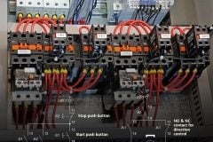
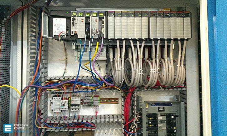 PLC Latch (Flip-Flop) Logic Function - Like a Sticky Switch! (photo credit: mbtmag.com)
- First scan of the PLC – indicating the PLC has just been turned on
- Time since an input turned on/off – a delay
- Count of events – to wait until set number of events have occurred
- Latch on or unlatch – to lock something on or turn it off
Let’s put some light on Latch/Unlatch Logic (or Flip/Flop) PLC Function.
Latches //
A latch is like a sticky switch – when pushed it will turn on, but stick in place, it must be pulled to release it and turn it off. A latch in ladder logic uses one instruction to latch, and a second instruction to unlatch, as shown in Figure 1 below.
The output with an L inside will turn the output D on when the input A becomes true. D will stay on even if A turns off. Output D will turn off if input B becomes true and the output with a U inside becomes true (Note: this will seem a little backwards at first).
The operation of the ladder logic in Figure 1 is illustrated with a timing diagram in Figure 2.
A timing diagram shows values of inputs and outputs over time. For example the value of input A starts low (false) and becomes high (true) for a short while, and then goes low again. Here when input A turns on both the outputs turn on.
There is a slight delay between the change in inputs and the resulting changes in outputs, due to the program scan time.
Here the dashed lines represent the output scan, sanity check and input scan (assuming they are very short.) The space between the dashed lines is the ladder logic scan. Consider that when A turns on initially it is not detected until the first dashed line. There is then a delay to the next dashed line while the ladder is scanned, and then the out- put at the next dashed line.
When A eventually turns off, the normal output C turns off, but the latched output D stays on. Input B will unlatch the output D. Input B turns on twice, but the first time it is on is not long enough to be detected by an input scan, so it is ignored. The second time it is on it unlatches output D and output D turns off.
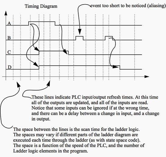
Dashed lines on timing diagram indicate PLC input/output refresh times. At this time all of the outputs are updated, and all of the inputs are read. Notice that some inputs can be ignored if at the wrong time, and there can be a delay between a change in input, and a change in output.
The space between the lines is the scan time for the ladder logic. The spaces may vary if different parts of the ladder diagram are executed each time through the ladder (as with state space code). The space is a function of the speed of the PLC, and the number of Ladder logic elements in the program.
The timing diagram shown in Figure 2 has more details than are normal in a timing diagram as shown in Figure 3. The brief pulse would not normally be wanted, and would be designed out of a system either by extending the length of the pulse, or decreasing the scan time.
An ideal system would run so fast that aliasing would not be possible.
A more elaborate example of latches is shown in Figure 4 below. In this example the addresses are for an older Allen-Bradley Micrologix controller. The inputs begin with I/, followed by an input number. The outputs begin with O/, followed by an output number.
A normal output should only appear once in ladder logic, but latch and unlatch instructions may appear multiple times.
In Figure 4 a normal output O/2 is repeated twice. When the program runs it will examine the fourth line and change the value of O/2 in memory (remember the output scan does not occur until the ladder scan is done.) The last line is then interpreted and it overwrites the value of O/2. Basically, only the last line will change O/2.
Flip-Flops //
Latches are not used universally by all PLC vendors, others such as Siemens use flip-flops. These have a similar behavior to latches, but a different notation as illustrated in Figure 5.
- The first rung shown has an input A connected to the S setting terminal. When A goes true the output value Q will go true.
- The second rung has an input B connected to the R resetting terminal. When B goes true the output value Q will be turned off.
The output Q will always be the inverse of Q. Notice that the S and R values are equivalent to the L and U values from earlier examples.
Understanding Latch/Unlatch Commands
Latching and Unlatching Conveyor
Reference // Automating Manufacturing Systems with PLCs – Hugh Jack
Related electrical guides & articles


Edvard Csanyi
Hi, I'm an electrical engineer, programmer and founder of EEP - Electrical Engineering Portal. I worked twelve years at Schneider Electric in the position of technical support for low- and medium-voltage projects and the design of busbar trunking systems.I'm highly specialized in the design of LV/MV switchgear and low-voltage, high-power busbar trunking (<6300A) in substations, commercial buildings and industry facilities. I'm also a professional in AutoCAD programming.
Profile: Edvard Csanyi

EEP represents for me, a great support since.since with your articles I will stay updated. Thanks.