PLC start up
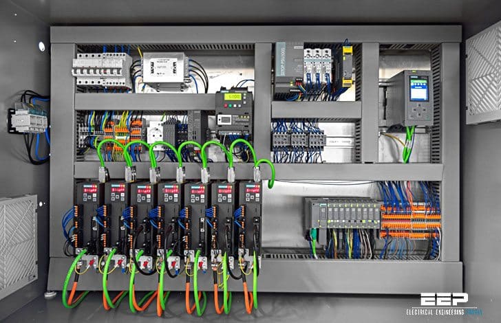
Prior to applying power to the system there are five important PLC start up and checking procedures to perform. User should make several final inspections of the hardware components and interconnections.

PLC start up and checking procedures before applying the power. However, this invested time will almost always reduce total PLC start up time, especially for large systems with many input/output devices.
Ok, let’s start with PLC star up and checking procedures:
- PLC prestart up procedures
- Static input wiring check
- Static output wiring check
- Control program review
- Dynamic system checkout
1. PLC prestart up procedures
The following checklist pertains to prestart up procedures:
- Visually inspect the system to ensure that all PLC hardware components are present. Verify correct model numbers for each component.
- Inspect all CPU components and I/O modules to ensure that they are installed in the correct slot locations and placed securely in position.
- Check that the incoming power is correctly wired to the power supply (and transformer) and that the system power is properly routed and connected to each I/O rack.
- Verify that the I/O communication cables linking the processor to the individual I/O racks correspond to the I/O rack address assignment.
- Verify that all I/O wiring connections at the controller end are in place and securely terminated. Use the I/O address assignment document to verify that each wire is terminated at the correct point.
- Check that the output wiring connections are in place and properly terminated at the field device end.
- Ensure that the system memory has been cleared of previously stored control programs. If the control program is stored in EPROM, remove the chips temporarily.
Go back to PLC start up procedures ↑
2. Static input wiring check
A static input wiring check should be performed with power applied to the controller and input devices. This check will verify that each input device is connected to the correct input terminal and that the input modules or points are functioning properly.
Proper input wiring can be verified using the following procedures:
- Place the controller in a mode that will inhibit the PLC from any automatic operation. This mode will vary depending on the PLC model, but it is typically stop, disable, program, etc.
- Apply power to the system power supply and input devices. Verify that all system diagnostic indicators show proper operation. Typical indicators are AC OK, DC OK, processor OK, memory OK, and I/O communication OK.
- Verify that the emergency stop circuit will de-energize power to the I/O devices.
- Manually activate each input device. Monitor the corresponding LED status indicator on the input module and/or monitor the same address on the programming device, if used.If properly wired, the indicator will turn ON. If an indicator other than the expected one turns ON when the input device is activated, the input device may be wired to the wrong input terminal. If no indicator turns ON, then a fault may exist in either the input device, field wiring, or input module.
- Take precautions to avoid injury or damage when activating input devices that are connected in series with loads that are external to the PLC.
Go back to PLC start up procedures ↑
3. Static output wiring check
A static output wiring check should be performed with power applied to the controller and the output devices. A safe practice is to first locally disconnect all output devices that involve mechanical motion (e.g., motors, solenoids, etc.).
When performed, the static output wiring check will verify that each output device is connected to the correct terminal address and that the device and output module are functioning properly.
The following procedures should be used to verify output wiring:
- Locally disconnect all output devices that will cause mechanical motion.
- Apply power to the controller and to the input/output devices. If an emergency stop can remove power to the outputs, verify that the circuit does remove power when activated.
- Perform the static check of the outputs one at a time. If the output is a motor or another device that has been locally disconnected, reapply power to that device only prior to checking.
The output operation check can be performed using one of the following methods:
Method #1 Assuming that the controller has a forcing function, test each output, with the use of the programming device, by forcing the output ON and setting the corresponding terminal address (point) to 1.
If properly wired, the corresponding LED indicator will turn ON and the device will energize. If an indicator other than the expected one turns ON when the terminal address is forced, then the output device may be wired to the wrong output terminal (Inadvertent machine operation does not occur because rotating and other motion-producing outputs are disconnected).
Method #2 Program a dummy rung, which can be used repeatedly for testing each output, by programming a single rung with a single normally open contact (e.g., a conveniently located push button) control- ling the output.
Place the CPU in either the RUN, single-scan, or a similar mode, depending on the controller. With the controller in the RUN mode, depress the push button to perform the test. With the controller in single-scan mode, depress and maintain the push button while the controller executes the single-scan.
Observe the output device and LED indicator, as described in the first procedure.
Go back to PLC start up procedures ↑
4. Control program review
The control program checkout is simply a final review of the control program. This check can be performed at any time, but it should be done prior to loading the program into memory for the dynamic system checkout.
When performed, this final program review will verify that the final hardcopy of the program, which will be loaded into memory, is either free of error or at least agrees with the original design documents.
The following is a checklist for the final control program checkout:
- Using the I/O wiring document printout, verify that every controlled output device has a programmed output rung of the same address.
- Inspect the hardcopy printout for errors that may have occurred while entering the program. Verify that all program contacts and internal outputs have valid address assignments.
- Verify that all timer, counter, and other preset values are correct.
Go back to PLC start up procedures ↑
5. Dynamic system checkout
The dynamic system checkout is a procedure that verifies the logic of the control program to ensure correct operation of the outputs. This checkout assumes that all static checks have been performed, the wiring is correct, the hardware components are operational and functioning correctly, and the software has been thoroughly reviewed.
Although small systems may be started all at once, a large system should be started in sections. Large systems generally use remote subsystems that control different sections of the machine or process. Bringing one subsystem at a time on-line allows the total system to start up with maximum safety and efficiency!
Remote subsystems can be temporarily disabled either by locally removing their power or by disconnecting their communications link with the CPU.


The following practices outline procedures for the dynamic system checkout:
- Load the control program into the PLC memory.
- Test the control logic using one of the following methods:
- Switch the controller to the TEST mode, if available, which will allow the execution and debugging of the control program while the outputs are disabled. Check each rung by observing the status of the output LED indicators or by monitoring the corresponding output rung on the programming device.
- If the controller must be in the RUN mode to update outputs during the tests, locally disconnect the outputs that are not being tested, to avoid damage or harm. If an MCR or similar instruction is available, use it to bypass execution of the outputs that are not being tested, so that disconnection of the output devices is not necessary.
- Check each rung for correct logic operation, and modify the logic if necessary. A useful tool for debugging the control logic is the single scan. This procedure allows the user to observe each rung as every scan is executed.
- When the tests indicate that all of the logic properly controls the outputs, remove all of the temporary rungs that may have been used (MCRs, etc.). Place the controller in the RUN mode, and test the total system operation. If all procedures are correct, the full automatic control should operate smoothly.
- Immediately document all modifications to the control logic, and revise the original documentation. Obtain a reproducible copy (e.g., DVD, etc.) of the program as soon as possible.
The PLC start up recommendations and practices presented in this technical article are good procedures that will aid in the safe, orderly start up of any programmable control system.
However, some controllers may have specific start up requirements, which are outlined in the manufacturer’s product manual. The user should be aware of these specific requirements before starting up the controller.
Go back to PLC start up procedures ↑
Reference // PLC Start Up and Maintenance by Industrial Text & Video Company


Thanks for the systematic procedure. Would like to add one point before powerup. Check Panel for proper Earthing (Grounding).
thanks a lot at all.
Your site is really good! This information is what I was looking for because I’m interacting with electrical and electronic engineers and I can instruct myself with their tasks as a mechanical project manager. Thumbs up!
Useful, applicable,thanks for ur information