
Estimated Study Time: 7 minutes
Construction of electrical assembly
Mounting of the different mechanical and electrical components (enclosures, busbars, functional units – circuit breakers, etc.) which constitute the LV switchboard defined by the original manufacturer must be carried out in compliance with the instructions (technical catalogue/assembly instruction manual) of the manufacturer.
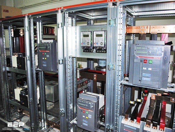 Practical advice for positioning of circuit breakers inside LV switchboard (on photo: ABB's ArTu K low voltage switchboard; credit: APK Mühendislik)
After the preparation of the loose parts to be assembled, the first step is constructing the metalwork structure.
For small and medium-size LV switchboards the insertion of the components inside the LV switchboard can be carried out more easily by arranging the enclosure horizontally on suitable trestles. Thus, working in this way it is possible to avoid keeping arms up and legs bent as it would be instead with an enclosure in a vertical position.
A further advantage as regards the internal accessibility is obtained by working without the metal side panels of the structure, thus leaving bare the whole internal wiring system.
Already at this stage, particular attention must be paid to respect the minimum creepage distances and clearances between the different live parts and the exposed conductive part.
Positioning of the circuit breakers
Here are some general indications for the best positioning of the circuit breakers inside the LV switchboard. It is the panel builder that, since he better knows the details of the plant, the installation place and the actual use, can design the switchboard front in an optimal way.
A good rule is trying to position the circuit breakers so as to shorten the paths of the higher currents, thereby reducing the power loss inside the LV switchboard with undoubted benefits from the thermal and economical point of view.
In the case of LV switchboards with a lot of columns, where possible it is advisable to position the main circuit breaker in the central column. In this way, the current is immediately divided into the two branches of the LV switchboards and the cross-sectional area of the main distribution busbars can be reduced.
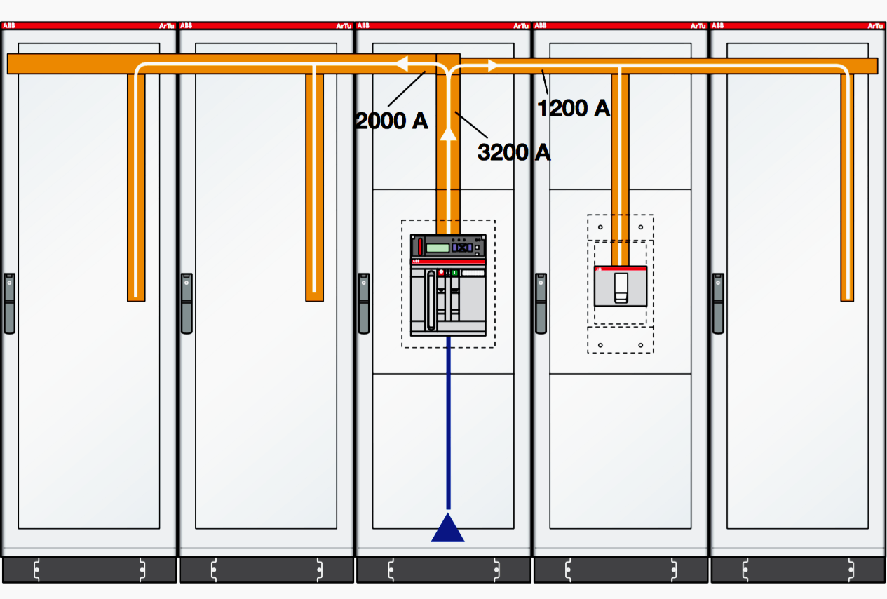
In the example given in the figure, the main busbar system can be sized for 2000 A, with a considerable economic advantage.

In this case, on the other hand, the main busbar system must be sized to carry 3200 A.
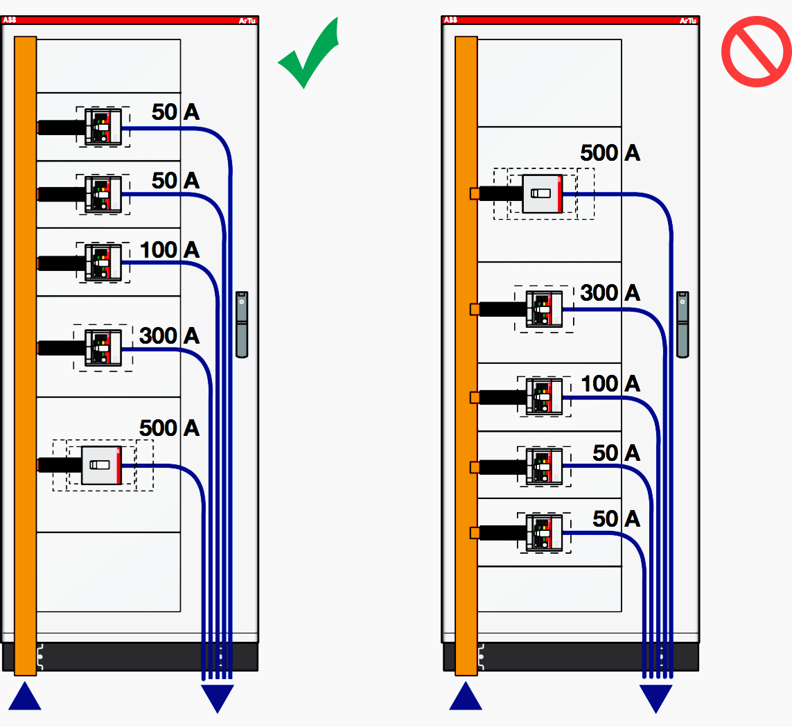
In electric switchboard the temperature varies vertically:
- The lowest areas are the coldest ones;
- The highest areas are the hottest ones.
For this reason, it is advisable to place the apparatus passed through by a current close to the rated value at the bottom (more loads) and at the top the apparatus passed through by a current far from the rated value (more discharges).

To facilitate the operation of large apparatus it is advisable to place them at a distance of 0.8 to 1.6 m from earth.
Anchoring of the conductors near to the circuit-breakers
It is necessary for the cables and busbars inside the LV switchboards to be fixed to the structure. In fact, during a short-circuit, the electrodynamic stresses generated in the conductors could damage the terminals of the circuit breakers.
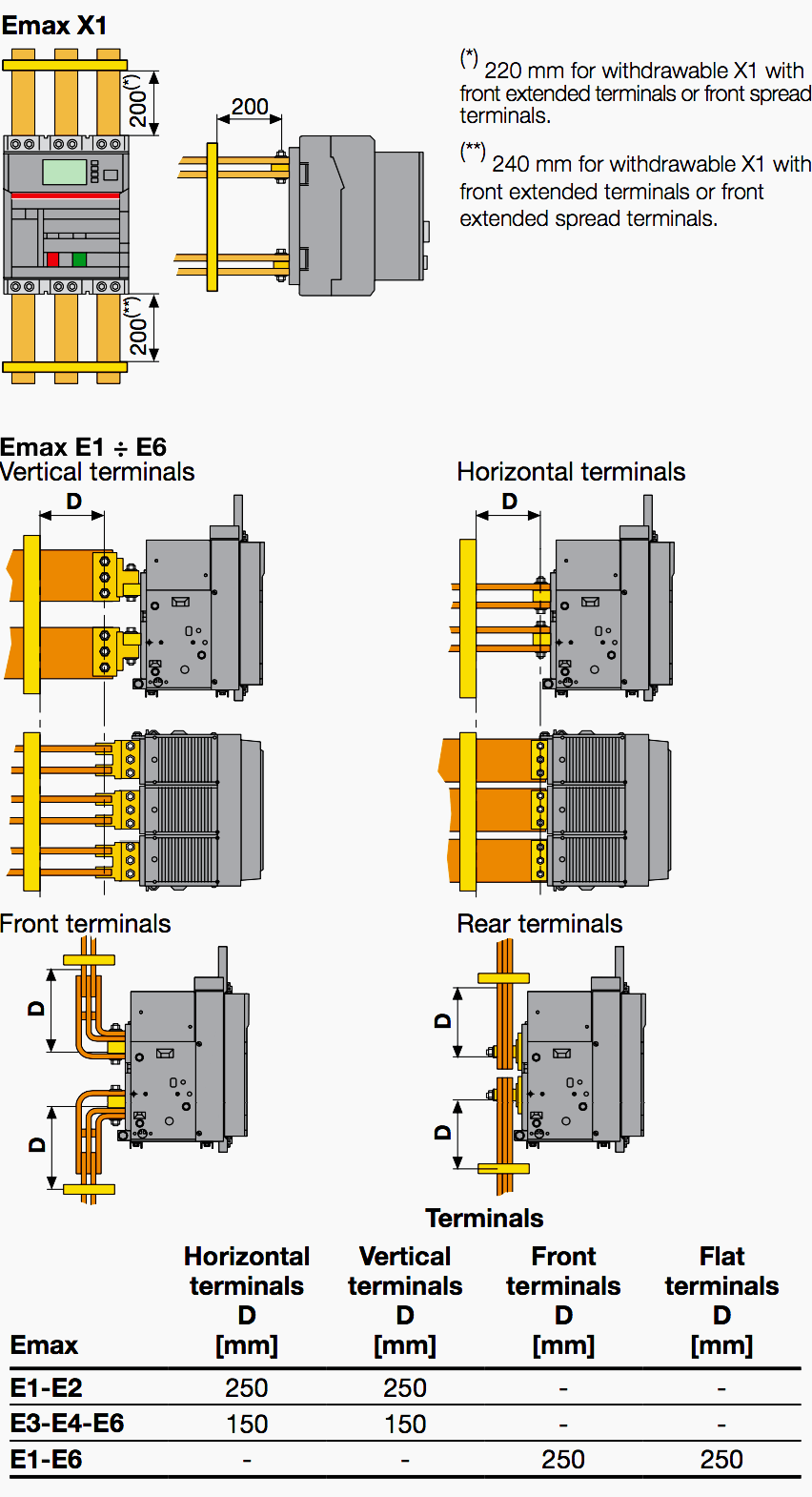
Emax circuit breaker
Figure 5 gives for Emax air circuit breakers an example of the maximum distance in mm (D) at which the first anchor plate of the busbars connecting to the circuit breaker shall be positioned according to the type of terminal and making reference to the highest admissible value of short-circuit current and of its relevant peak.
For further details reference shall be made to the technical catalogues and the circuit breakers manuals.
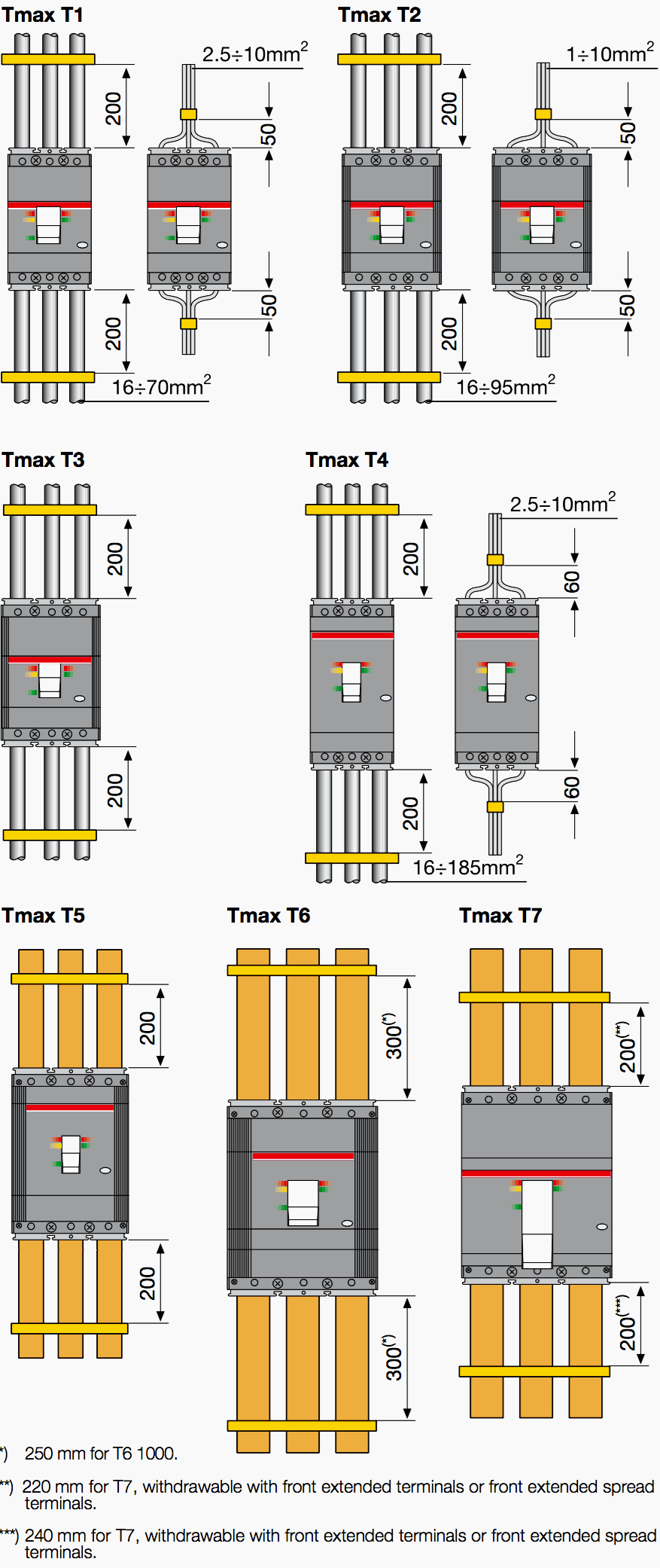
Tmax circuit breaker
Figure6 gives for Tmax molded-case circuit breakers an example of the suggested maximum distance in mm at which the first anchor plate shall be positioned according to the type of terminal and making reference to the highest peak current value admitted for the circuit breaker.
For further details reference shall be made to the technical catalogues and the circuit breakers manuals.
Reference // Practical indications for the construction of assemblies by ABB
Related electrical guides & articles


Edvard Csanyi
Hi, I'm an electrical engineer, programmer and founder of EEP - Electrical Engineering Portal. I worked twelve years at Schneider Electric in the position of technical support for low- and medium-voltage projects and the design of busbar trunking systems.I'm highly specialized in the design of LV/MV switchgear and low-voltage, high-power busbar trunking (<6300A) in substations, commercial buildings and industry facilities. I'm also a professional in AutoCAD programming.
Profile: Edvard Csanyi

Thanks for your informations on this.
Is there any another brand , like schneider or mitsubishi (ACB, MCCB).?
Traiwit
Dear Sir
I Would like to have this article, so how Can I get it. And i Would like to improve my knowledge in diesel generator. Specially to understand how cai I regulate the AVR or engine frequency.
Many Tks.
So, I receive a lots of knowledge and how can I get this article…
Thanks a great deal Sir, for this kind dedication
Thank you very much for guide to Low Voltage Circuit Breakers Standard and on how to Design a Low Voltage Switchboard, but we need also Medium Voltage 13.8 kV for Substation.
Very Good and detailed article.
Thanks Edward Such a Nice Information..With regards, Swanand Desai
nice article! thanks for the information
thank you
I want more information for vaccum contactor 400A/7.2 KV ALSTOM
Congrats Edvard, great article!!!
Thanks for all this beacuse I receive lots of knowledge from one portal such a great structure
Well done!
Thank you Mike!
IN ABOVE PANEL ALL CIRCUIT BREAKERS HAVING SAME SHORT CIRCUIT CAPACITY OR DIFFERENT AS PER BUS BAR BRANCH ?
Very good article;practical insights
A number of experiences with various switchboard builders LV MCCs has also found the spacing from the module walls and insulation of the line side conductors to the CB to be important in preventing line side arcing faults being initiated by hot arc chute vent gases during fault clearing. This is particularly true at the higher voltages eg 690V.
Thank you Edvard for your dedication to the profession.