
Estimated Study Time: 43 minutes
Why power correction?
All modern electronic devices are vulnerable to the poor power quality. But why? What can you do about it? This technical article describes 12 types of power correction devices (16 in total) that accept electrical power in whatever form it is available and modify the power to improve the quality or reliability required for electronic AC equipment.
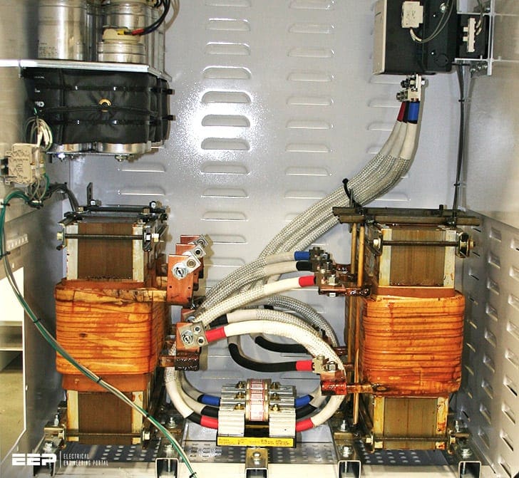 16 power correction devices available to install and really improve the power quality (on photo: Input filter that conditiones the waveform of the power system to meet IEEE519 power quality guidelines. It is designed to with a dedicated trap circuit tuned to the appropriate multiples the fundamental frequency to mitigate the harmonic content. Credit: SUBCOE)
These devices perform functions such as the elimination of noise, change, or stabilization of voltage, frequency, and waveform.
The power handling and performance requirements vary depending upon each application. A wide variety of power correction products are available that utilize a range of technologies and provide different degrees of protection to the connected load.
The job of selecting the appropriate power correction device is fairly straightforward when it powers a single load. The requirements of only one load need to be considered.
For larger systems that support many loads, the requirements of all loads need to be considered, as well as the potential interactions between them, to decide the appropriate enhancement equipment and system construction.
- Isolation transformers
- Noise filters
- Harmonic current solutions
- Transient voltage surge suppression
- Voltage regulators
- Power line conditioners
- Computer power distribution units
- Magnetic synthesizer
- Motor – alternator / generators
- Static transfer switches (STSs)
- Standby power systems (SPSs)
- Uninterruptible power supplies (UPSs)
1. Isolation transformers
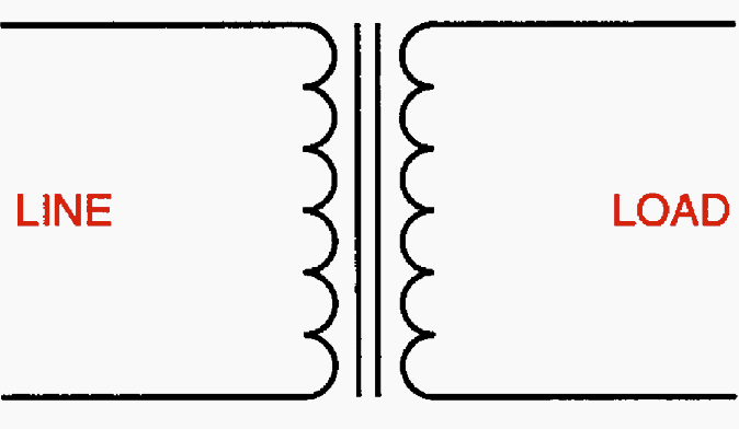
Isolation transformers are one of the most widely used power correction devices. Figure 1 depicts the configuration of an isolation transformer. They incorporate separate primary (or input) and secondary (or output) windings.
They provide for several functions.
Another function of the separate windings is to provide for establishing the power ground reference close to the point of use.
This greatly reduces the problem of common-mode noise induced through “ground loops” or multiplecurrent paths in the ground circuit upstream of the established reference ground point.
These passive devices introduce minimal current distortion onto the input source. In addition, they can reduce the triplen harmonic currents fed back to the source by single-phase nonlinear loads.
Other positive and negative sequence harmonic currents are affected by the 30° fundamental frequency phase shift of the delta-wye transformer.
For example, the 5th and 7th harmonic load currents are inverted, which can be beneficial in providing cancellation of these harmonic currents at the primary voltage level.

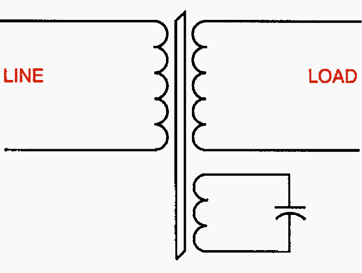
For power conditioning purposes, isolation transformers should be equipped with electrostatic (Faraday) shields between the primary and secondary windings as shown in Figure 2 above.
An electrostatic shield is a conducting sheet of nonmagnetic material (copper or aluminum) connected to ground that reduces the effect of interwinding capacitive coupling between primary and secondary windings and improves the isolation transformer’s ability to isolate its load from the common-mode noise present on the input power source.
Simple shielding adds little to the cost, size, or weight of the transformer.
Specialty conditioning transformers, referred to as super isolation or ultra isolation transformers, are equipped with additional shields around each winding to further reduce the capacitive coupling.
These transformers generally do not provide decoupling of the normal-mode disturbances, such as sags, swells, and surges.
Isolation transformers do not provide any line voltage regulation and, in fact, may cause some additional degradation of voltage regulation due to their series impedance.
As was stated, shielding tends to adversely affect regulation. Isolation transformers tend to be quite efficient (95% to 98%) so they generate little heat and are relatively quiet. They can be obtained in enclosures that are suitable for installation in computer rooms.
Isolation transformers can be installed separately or with power distribution circuit breakers and monitoring circuits. Isolation transformers with distribution circuit breakers can be located near the critical load.
This configuration provides for short power feeders and branch circuits, thus limiting susceptibility to coupled noise. Isolation transformers incorporated into packaged power distribution units (PDUs) often include additional noise and surge suppression, integral power distribution, monitoring, and flexible output cables that provide for simpler rearrangement of the load equipment.
2. Noise filters
Noise filters reduce conducted electromagnetic interference (EMI) and radio-frequency interference (RFI). Figure 3 shows a representation of one type of inductor/capacitor (LC) filter.
Most types of electronic equipment have some form of filters to limit the high-frequency noise, usually needed to comply with Federal Communications Commission (FCC) equipment emission limits.
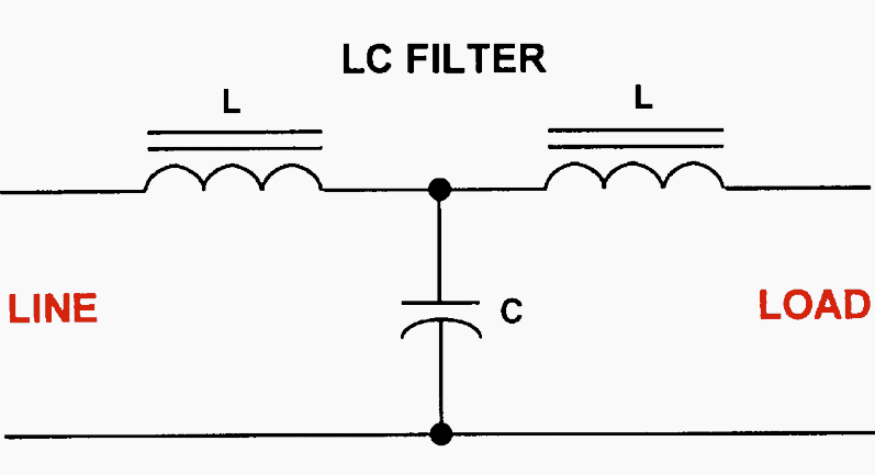
The simplest form of filter is a “low pass” filter designed to pass 60 Hz voltage but to block the higher frequencies or steep wavefront surges. These devices contain series inductors followed by capacitors to ground. The inductor forms a low-impedance path for the 60 Hz utility power, but a high-impedance path to the high-frequency noise.
The capacitor conducts the remaining high-frequency noise to ground before it reaches the load.
RFI filters are not effective for frequencies near 60 Hz, such as low-order harmonics.
Filters can be connected line-to-line or line-to-neutral for rejection of normal-mode noise. They can also be connected line-to-neutral and line-to-ground or used in conjunction with a balun transformer to reduce common-mode noise between any of the conductors.
Filters require careful application!! If not used properly, they can cause a ringing effect that can be worse than the noise they were intended to filter. For this and other reasons, filters larger than simple RFI filters are seldom used as add-on line-conditioning devices.
3. Harmonic current solutions
A number of alternative methods have been employed to reduce or control harmonic currents. Methods include passive harmonic filters, transformer-based solutions, and active harmonic filters.
3.1 Passive harmonic current filters
Passive harmonic current filters are used to prevent the harmonic currents of nonlinear loads from being fed back into the power source where they cause heating of conductors and transformers and corresponding voltage distortion.
Passive filters contain only inductors, capacitors, and resistors.
Two types of passive harmonic current filters are parallel-connected series-resonant filters and series-connected parallel-resonant filters. A typical series-resonant filter is shown in Figure 4.
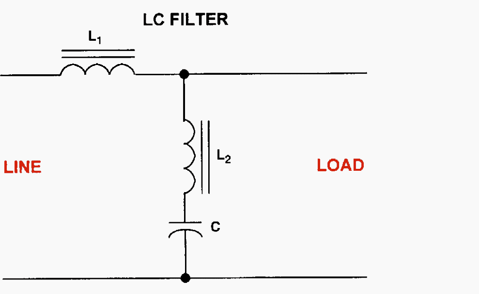
The filter is placed in parallel with the load, and the filter is tuned for the lowest predominant harmonic frequency generated by the load or observed in the power system.
For diode rectifier nonlinear loads, there are significant levels of harmonic currents without any appreciable fundamental reactive power (VARs).
A potential disadvantage of passive series-resonant harmonic filters in this case is the leading power factor due to the fundamental VARs of the filter’s capacitors. For changing loads, a stepped filter can be obtained that switches in and out the requisite number of filter steps as the load increases or decreases.
Series-connected parallel-resonant harmonic current filters have been applied to control the flow of harmonic currents by intentionally inserting a high impedance at the target harmonic current frequency.
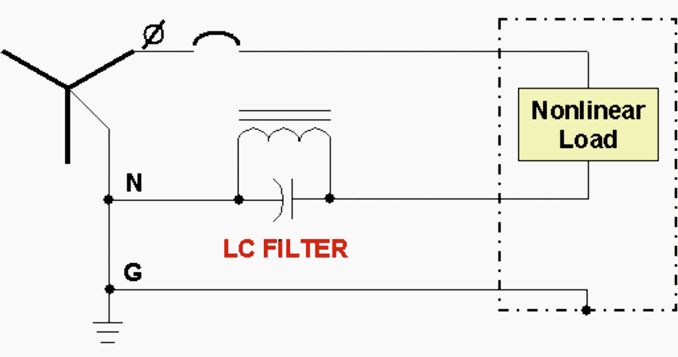
Figure 5 depicts a parallel-resonant filter in a typical application where the parallel-resonant filter is tuned to the 3rd harmonic to block the flow of triplen harmonic neutral current in three-phase power systems.
The filter eliminates the need for oversized neutral wires to handle the combined triplen currents from the phases, and standard wiring practices can be used.
A potential disadvantage of the series-connected parallel-resonant filter is the resulting increased levels of voltage distortion observed on the load side of the filter.
3.2 Transformer-based harmonic current reduction
Three basic types of transformers applied to reduce harmonic currents are:
- Delta-wye isolation transformers,
- Zigzag auto-transformers, and
- Phase-shifting, multi-winding transformers.
Delta-wye isolation transformers
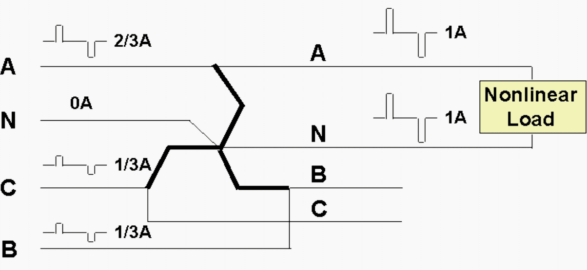
Delta-wye isolation transformers, which are in widespread use as three-phase power distribution transformers, provide cancellation of the triplen harmonic load currents as they circulate in the delta primary windings.
Zigzag transformers
Zigzag transformers, sometimes called zero-sequence transformers, are used to control the flow of triplen harmonic currents, diverting them from overloaded feeders or distribution transformers.
Figure 6 shows a typical zigzag transformer application.
The transformer is, connected in parallel to the three-phase and neutral wires, providing a low-impedance path to triplen harmonics. The triplen harmonic currents are shunted through the zigzag transformer and thus diverted away from the input feeder or supply transformer.
However, triplen harmonic currents continue to flow in all the wires downstream of the zigzag transformer, and doubled neutrals or other harmonic current coping means are still required.
Phase-shifting, multi-winding transformers
Phase-shifting, multi-winding transformers can be used on three-phase power systems to cancel certain orders of harmonic currents, depending on the particular phase shift provided by the transformer windings.
Other multi-winding transformers have been applied with rectifier circuits to provide cancellation of more orders of harmonic currents, particularly in high power rectifier applications, such as large motor drives.
For electronic loads operating on line-to-neutral voltages, a number of multi-winding transformers have been devised that create multiphase, line-to-neutral voltages.
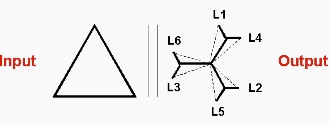
Figure 7 above is an example of a six-phase multi-winding transformer used to cancel 5th and 7th order harmonic load currents.
Thus a single transformer can cancel triplen, 5th, and 7th harmonic load currents. Since the reduction in the harmonic currents is by cancellation, the loading on each transformer output needs to be equal and balanced.
3.3 Active harmonic current filters
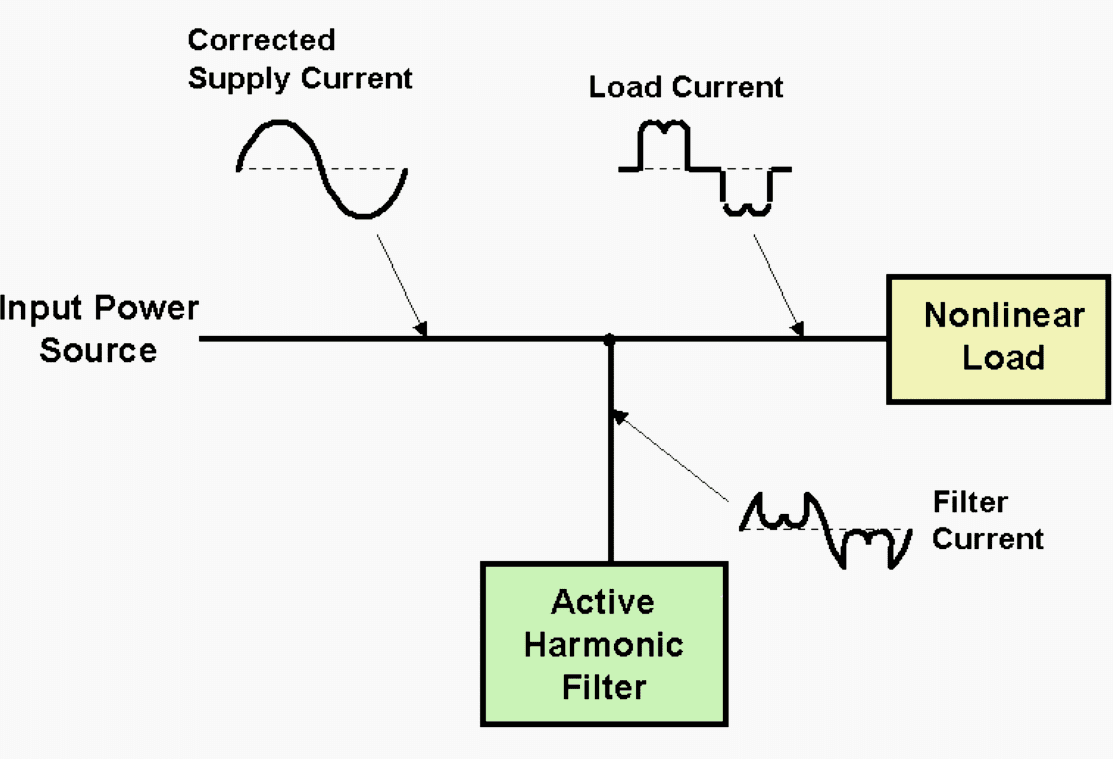
Active harmonic current filters are electronic devices that sense on a real-time basis the harmonic load currents and inject equal and opposite harmonic currents to cancel harmonic load currents. Figure 8 depicts a typical implementation of an active harmonic current filter.
Harmonic current flows are generally reactive current flows and require minimal levels of real power to cancel.
Certain implementations of active harmonic current filters can also provide fundamental frequency reactive currents to provide total power factor correction.
However, they can adapt to changing load conditions. Being electronic circuits, they are inherently more complex and less reliable than passive filters and, to date, have been significantly more expensive.
4. Surge suppressors
Surge suppressors encompass a broad category surge protective devices (SPDs) from large devices, such as lightning-surge arrestors, to small transient voltage surge suppressors (TVSSs) used to protect plug-connected devices.
Effective surge protection for an entire building power distribution system requires the coordinated use of large-capacity current-diverting devices at the service entrance followed by lower capacity voltage-clamping devices applied strategically throughout the power system.
The service entrance devices are intended to lower the energy level of a very large surge to that which can be handled by other devices closer to the loads. If improperly coordinated, excess energy can destroy the downstream suppressors and damage the connected load equipment.
The smaller surge suppressors are generally simple, and relatively low-cost, devices. They usually contain metal-oxide varistors, avalanche diodes, or other voltage-clamping devices that are connected across the power line or from one phase-voltage lead to another or to ground.
Because of their small size and low cost as compared with the equipment they serve and the cost of determining if such surges exist at a given installation (or even if this feature is already built into the computer itself), they are often routinely used as low-cost insurance against the chance of severe surges.
Many of the higher quality line conditioners include suppressors. They can be added to a distribution panelboard serving electronic loads if not included elsewhere.
The most effective locations for surge suppression is at the service entrance, at the output of separately derived sources (where the neutral is bonded to ground), and at the source of severe transient voltage surges, such as switched inductors, contactor coils, etc.
Surge suppression devices are packaged into various assemblies that often include power receptacles for several loads. These units are most commonly sold for use with small, single-phase loads and are available from a variety of manufacturers.
The bad thing is that SPD may fail without any indication, leaving the load unprotected.
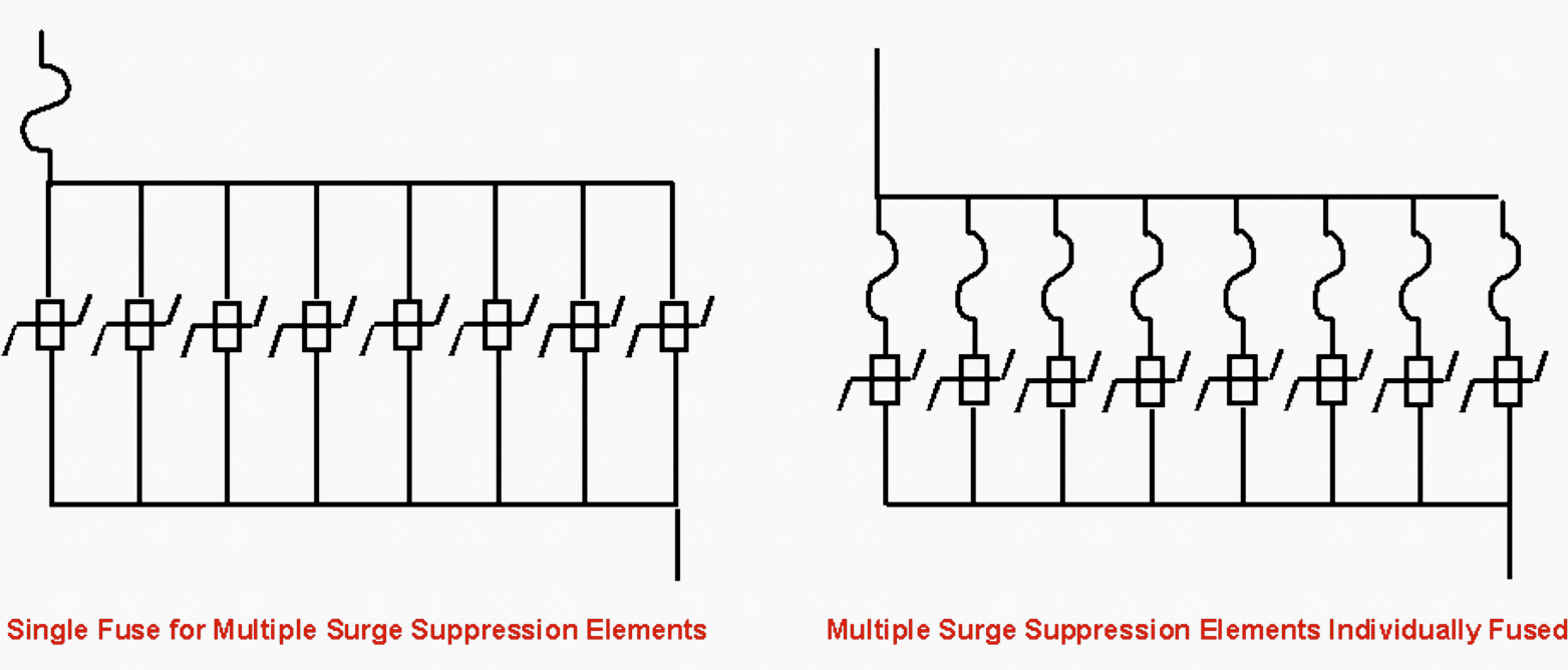
Figure 9 shows a typical parallel-connected, multimode surge suppressor.
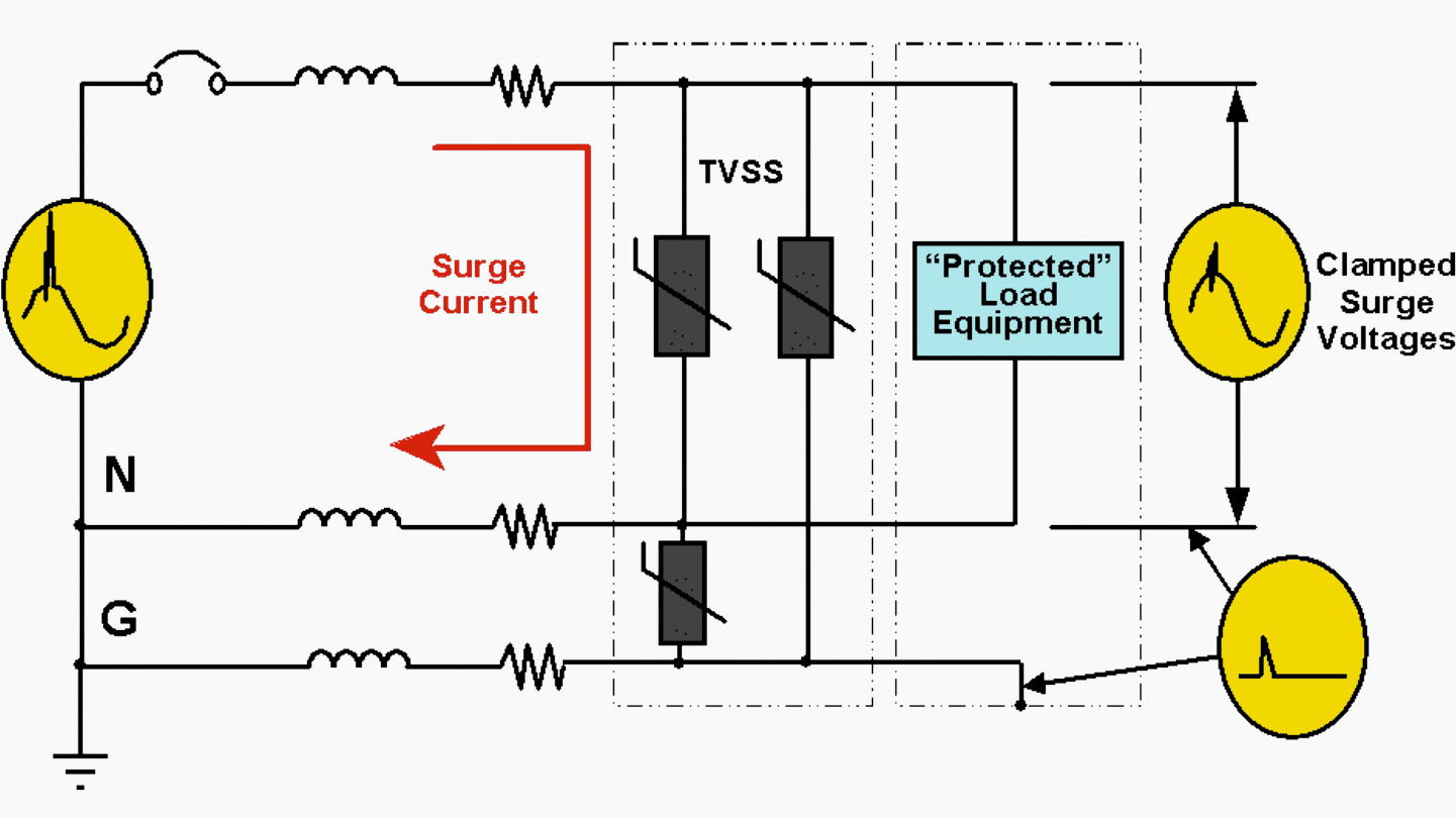
Figure 10 shows a typical parallel-connected surge suppressor using multiple, individually fused surge suppression elements.
5. Voltage regulators
Most low-frequency voltage disturbances, except very deep sags or outages, can be handled by appropriate application of a voltage regulator. There are a number of types of voltage regulators in use today.
These units are not suitable to protect electronic loads against rapid changes in voltage.
5.1 Tap changers
Fast response regulators divide into two generic classes: tap changers and buck boost. The first is the tapchanging regulator shown in Figure 11.
Quality tap changers are designed to adjust for varying input voltages by automatically transferring taps on a power transformer (either isolating type or auto-transformer type).
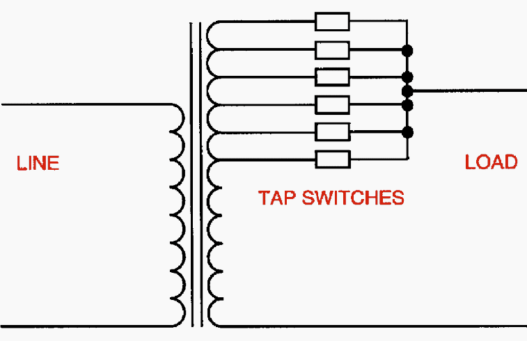
The number of taps determines the magnitude of the steps and the range of regulation possible. An acceptable regulator should have at least four taps below normal and two taps above normal for seven total steps. The taps are typically in 4% to 10% steps, depending on specific designs.
Response time is usually less than two cycles and is limited to that speed because of the zero current-switching and controls-stability criteria.
It also has high short-term overload capability to provide for starting or inrush currents. In its usual configuration with an isolating transformer and wide undervoltage capability, it provides both common-mode noise isolation and voltage regulation.
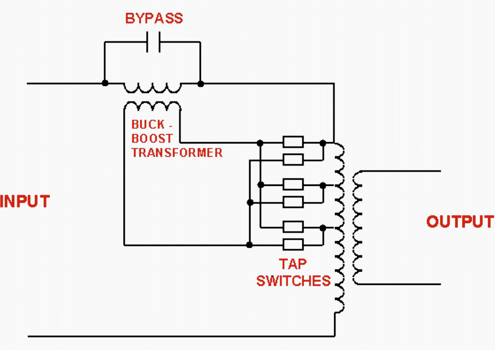
A variation of the traditional tap-changing regulator is the use of a series injection transformer to allow smaller current tap-changing semiconductors to be used in a buck-boost mode.
See Figure 12 below.
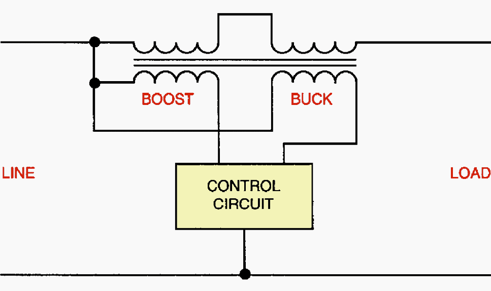
5.2 Buck boost
The second class of fast response regulators is the electronic buck-boost type (Figure 13). It utilizes thyristor control of buck and boost transformers in combination with parametric filters to provide regulated sinusoidal output, even with nonlinear loads typical of computer systems.
This is done in a smooth continuous manner eliminating the steps inherent in the tap changer. Inrush currents can be delivered for start-up typical of computer central processors or disc drive motors while maintaining nearly full voltage.
Units can be equipped with an isolation transformer with electrostatic shield providing voltage step-down and common-mode attenuation when needed. Power is fed to the regulator, which either adds to (boosts) or subtracts from (bucks) the incoming voltage so that the output is maintained constant for 15% to 20% variations of input voltage.
A parametric filter provides a path for nonlinear currents generated by the load and by the regulator itself and produces a sine wave output with low total harmonic distortion.
5.3 Ferroresonant constant voltage transformers
One common type of voltage regulator is a ferroresonant or constant voltage transformer (CVT). Figure 14 represents one design topology of a ferroresonant regulator. This class of regulators uses a saturating transformer with a resonant circuit made up of the transformer’s inductance and a capacitor.
These units are reliable because they contain no moving or active electronic parts. If these units are built with isolation (and shielding), they can provide for common-mode noise reduction and provide a separately derived source for local power grounding.
They also provide normal-mode noise reduction, voltage distortion isolation, and transient voltage surge protection.
Careful application is required to avoid unwanted load-source interactions. The load current tends to cause the unit to go out of resonance if it gets too high.
The other devices on the output of the CVT will see this sag in the voltage and may shut down due to an undervoltage. These devices should be oversized if they are expected to provide for heavy starting or inrush currents or to provide very deep sag protection.
Ferroresonant transformers create more audible noise than regular transformers and may require special enclosures before they can be installed in office environments.
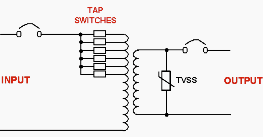
6. Power line conditioners
Typical power line conditioners combine one or more of the basic power correction technologies to provide more complete protection from power disturbances.
Some power line conditioners combine the noise-reduction features of isolation transformers or filtering devices with voltage regulators.
Figure 15 depicts a power line conditioner using tap-switching voltage regulator, isolation transformer, and surge suppression.
7. Computer power distribution units (PDUs)
A PDU is a device that provides a convenient method for distributing electrical power to information technology equipment (ITE) without the need for premises wiring, and typically includes a separately derived source for local grounding.
See Figure 16 below.
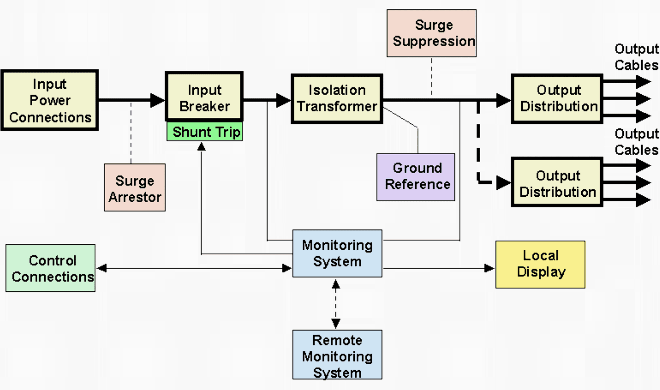
The load cables are terminated with mating connectors for connecting to the ITE. Some manufacturers include power conditioners such as tap changers, motor – alternator / generator (M-Gs) sets, or magnetic synthesizers internal to the PDU to further enhance performance.
The PDU greatly reduces the time required to install the average information technology system and allows for relatively easy relocation of equipment as compared to hard wiring methods. This can translate into significant cost and time savings.
The isolation provided by the transformer (or M-G) in the PDU allows the creation of a separately derived source and common grounding point.
PDUs with internal voltage regulators can be used to reduce the effects of long distribution feeds from central power conditioning or uninterruptible power supply (UPS) equipment.
The effect of current harmonics on the power source is a function of the type of conditioner used in the PDU.
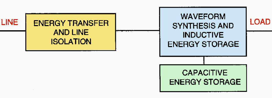
8. Magnetic synthesizer
Another ferroresonant-based technology is the magnetic synthesizer (Figure 17). These units are three-phase systems consisting of nonlinear inductors and capacitors in a parallel-resonant circuit with six saturating pulse transformers.
These units draw power from the source and generate an output voltage waveform by combining the pulses of the saturating transformers in a step-wave manner.
Additional filtering is included to eliminate self-induced harmonics. This filtering can handle a reasonable level of harmonic distortion at the input or at the output as induced by the nonlinear loads. The circuit is tuned to the rated output voltage and frequency.
The magnetic synthesizer has an inherent current-limiting characteristic that limits maximum current at full voltage to the range of 200% to 250% of rating. Beyond that load, the voltage drops off rapidly, producing typically 250% to 300% current at short circuit.
This is a limitation with large inrush and starting currents.
Sudden large load changes, even within the unit’s rating, can cause significant output voltage variations. These units are best applied when the load does not make large step changes. The ferroresonant circuit has stored energy and may ride through outages of one half-cycle or more depending on unit loading.
Magnetic synthesizers tend to be large and heavy due to the magnetics involved and can be acoustically noisy without special packaging. Some of the larger units display good efficiencies as long as they are operated at close to full load.
The magnetic synthesizer provides two-way harmonic isolation, isolating the electronic load from supply voltage distortion and isolating the supply from the load current distortion.
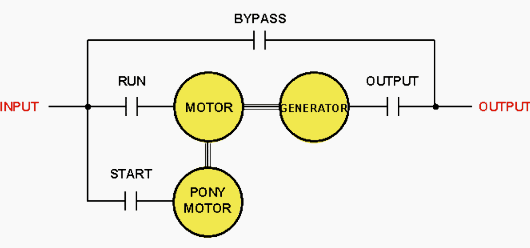
9. Motor-alternator/generators
M-Gs provide the function of a line conditioner and can also provide for conversion of the input frequency to a different frequency that is required by the load. Figure 18 depicts one configuration of an M-G.
Examples of this are 60-to-50 Hz or 60-to-400 Hz frequency converters. These units consist of a utility-powered electric motor driving an ac generator that supplies voltage to the load. The motor and generator are coupled by a shaft or belts.
This totally mechanical coupling of the input and the output allows the M-G to provide total electrical noise isolation of the load from the input power source.
The induction motor is the least expensive of the common types of motors used on these devices. This type of motor does not rotate at the same speed as the rotating field that is generated by the input power. The speed at which the motor turns changes with load and input voltage variations. Since the generator
frequency is a function of its shaft speed, the output frequency varies with the motor speed.
IMPORTANT! The output voltage is maintained by controlling the excitation to the field winding of the generator and is independent of small changes of motor speed.
Although most of today’s computer power supplies can operate with a wide range of frequency, some loads may be frequency sensitive (e.g., ±0.5 Hz tolerance). For critical frequency applications, low slip induction motors or synchronous motors should be used.
The output frequency of a synchronous M-G is the same as the input frequency. However, the synchronous M-G output voltage is not in-phase with the input power source and varies proportionate to the loading. Uninterrupted transfers between the M-G and bypass source for maintenance must accommodate the varying output phase angle of the M-G.
For induction M-Gs, uninterrupted transfers to bypass can be accomplished only during the brief periods of time when the output voltage is nearly in-phase with the bypass voltage.
Products are available that are able to maintain output frequency even while the shaft speed is slowing down. These devices do not have fixed poles in the generator. Instead, the poles are created or “written” as the device rotates. When input power is lost and the shaft speed starts to decay, the spacing of the poles is reduced and their number is increased so that the frequency remains constant.
This method achieves ride-through times that are significantly longer than other M-G sets with the same rotating energy at the cost of increased complexity and lower efficiency.
M-Gs tend to be more expensive than other types of line conditioning equipment. They are usually physically large and heavy. Depending on the design, the M-G efficiency can be relatively low so that electrical energy costs over its lifetime may be significant.
10. Static transfer switches (STSs)
STSs use semiconductor switches to provide very fast, break-before-make switching between two independent power sources and are applied to improve the quality and reliability of power to the connected loads.
Figure 19 depicts a typical STS incorporating maintenance bypass provisions to each input source.
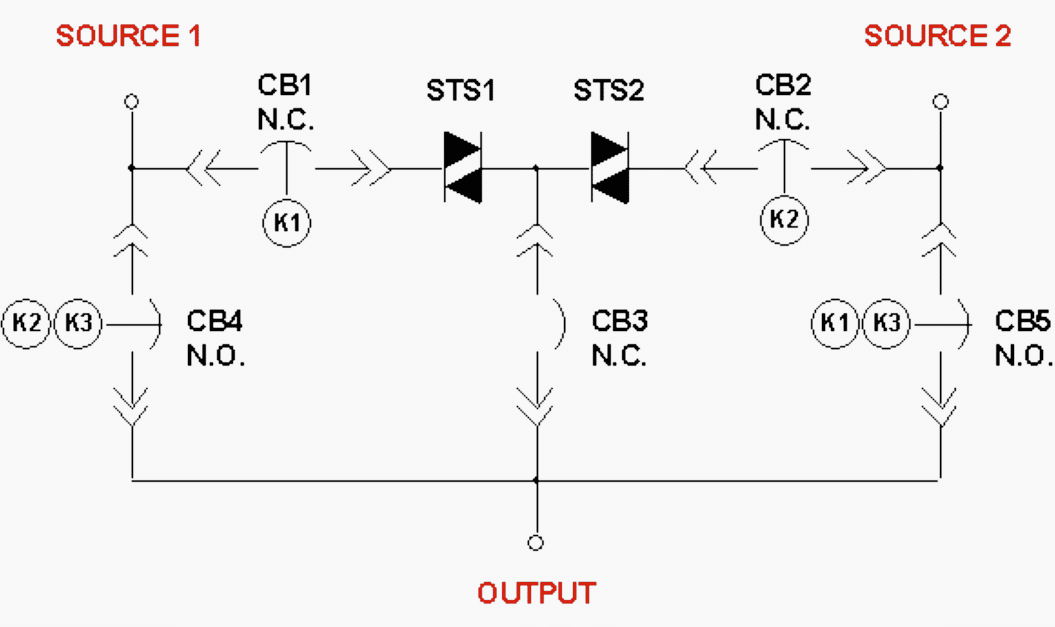
Proper application of STSs require the two input power sources to be as independent as possible so that there are no simultaneous power source failures. Both input sources need to be synchronized within 10° to 15° to keep from causing sudden phase shifts during transfers that can upset the load equipment.
Also both input sources need to be nominally available so that the STS has an alternate source available to transfer to in case of switch failure (analogous to having a bypass source available for UPS systems).
STSs have been applied at both the medium (up to 34 kV) and low (<600 V) voltages.
As with most power conditioners, application as close to the protected load as possible yields the greatest protection.
11. Standby power supply
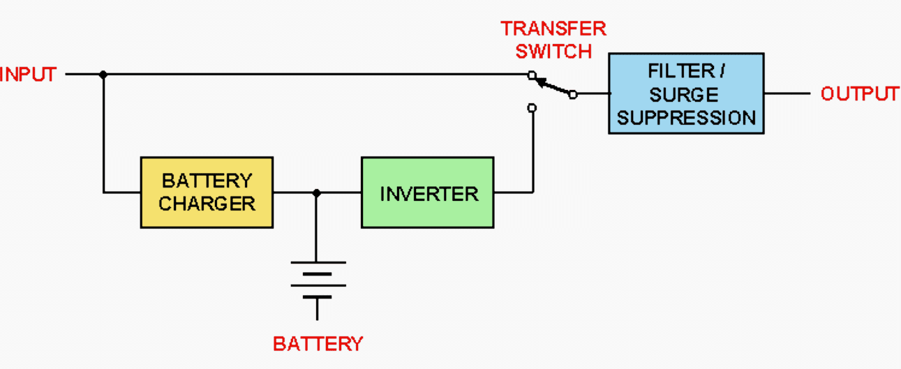
Standby power supplies are back-up power systems in which the load is normally supplied by the input power source. Figure 20 shows one configuration of the standby power supply.
These power systems are intended for loads that can tolerate a discontinuity of power during the transfer. They come in a number of configurations using a number of technologies and are used for a variety of loads ranging from personal computers to emergency lighting.
There are significant variations in the power failure detection and transfer times and the type of output waveform supplied when the normal power source is not available.
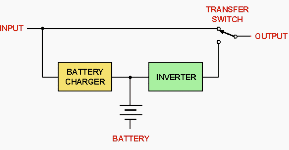
The simplest form of standby power supply has the load connected to the input power source through a transfer switch during normal operation.
The design of this type of supply allows several economies. First, the inverter is not supporting the load on a continuous basis. It only has to operate for the duration of the power outage or for the support time of the batteries.
This period is typically 15 min or less.
The quality of the inverter output waveform is generally less than for an on-line UPS. Second, the rectifier section only has to recharge the battery and not support the full load of the inverter.
Normal operating efficiency of this type of unit is high since the load is being fed from the utility under normal operation. The losses are those associated with the line conditioning element (if used) and the battery charging circuit.
A major requirement of this type of unit is its ability to sense all types of power failures and transfer to the inverter without an unacceptably long input-power loss to the load equipment.
These units are typically successful in powering systems that have power supplies that can tolerate short durations of input-power interruption. They are often employed with loads that utilize switch-mode power supplies, which often do not require regulated voltage and are tolerant of momentary loss of power during the transfer.
A common enhancement of the standby power supply involves the use of some form of power conditioner in series with the load to provide conditioning of the supply voltage during normal operation as shown in Figure 21 above.
The conditioner can be one of the types that were previously discussed.
Some manufacturers take advantage of the extensive capability of some of the conditioners, such as the ferroresonant transformer, magnetic synthesizer, and
M-G. The filtering capability allows them to use a very simple inverter circuit that generates square waves as opposed to sine waves. The line conditioner is in circuit all the time and provides conditioning of the inverter output as well as the utility during normal operation.
Continuous regulated output power can be achieved by this method if the line conditioner has sufficient ride-through to power the load during the interruption time.
12. Uninterruptible power supplies (UPSs)
UPSs are intended to provide regulated, uninterrupted output power regardless of the condition of the input power source, including total power outages. UPSs come in a variety of configurations and utilize various technologies.
The major categories of UPS are rotary and static UPS.
Since UPSs were discussed in some earlier articles and guides, we won’t describe them again. However, feel free to find all information about UPS devices here.
Reference // Powering and Grounding Electronic Equipment by IEEE
Related electrical guides & articles


Edvard Csanyi
Hi, I'm an electrical engineer, programmer and founder of EEP - Electrical Engineering Portal. I worked twelve years at Schneider Electric in the position of technical support for low- and medium-voltage projects and the design of busbar trunking systems.I'm highly specialized in the design of LV/MV switchgear and low-voltage, high-power busbar trunking (<6300A) in substations, commercial buildings and industry facilities. I'm also a professional in AutoCAD programming.
Profile: Edvard Csanyi

Very powerful note
Excellent information, real useful
Thanks a lot
Dear Sir
please clarify whether passive filter applicable for variable load because supplier is telling passive filter not possible for variable like that
please note that below supplier concern and customer answer.
**//
1. SUPPLIER CONCERN : Regarding sub-supplier for Passive filter several manufacturer such as ABB, SCHNIDER, SCHAFFNER regret to supply the Passive filter (based on project requirements) due to the involvement of risks and mal-operations of the products under varying load conditions for respective system.
Presently, only another sub-supplier SAMWHA, Korea has provided basic parameters, for critical components such as capacitor, Reactor based on simulation results/ inputs from TSHJ. However, this sub-supplier has also mentioned that the proposed components details are solely based on the fixed rated capacity of the filter bank and the performance of the passive filter might be affected/ not guaranteed under varying load conditions (several cases for ON/OFF of the motor loads /VSD based on the process operations).
OUR CUSTOMER ANSWER: As indicated before, We made all calculation under load varying and the passive filter requested complied to reduce the 5th harmonic to client requirements as well as not produce any resonance neither overvoltage.
2. SUPPLIER CONCERN : The desired location of the passive filter should be after the incoming source and before the loads (series connections) for satisfactory operations of passive filter. However, presently it is not possible to apply the passive filter in between Incoming panels & MC panels, since all the LV EB/MC are already installed at package S/S and it is not feasible to install the Passive filter panels as required locations.
It is requested to review the installation location of the passive filter and provide suggestion/ alternative solution accordingly.
OUR CUSTOMER ANSWER: Passive filter has been Validated and modeled in ETAP connected in parallel . ( WYE(Y) connected). and the results is satisfactory as indicated before.
WE ARE SUBCONTRACTOR WE WANT TO KNOW THE REAL THINGS WHOSE SAYING IS CORRECT. BECAUSE WE ARE NOT AWARE OF FILTER.
kindly reply the solution immediately
Hello Edward,
Your article was very informative and useful for me as a journeyman consultant from Meralco Power Academy, Ph. Thanks so much and regards.
Dear Edvard,
It’s me again. I tried to make a copy of the full content but it was not successful about some pictures. It possible to send me by email?
Thanks in advance,
Mohammad
Hello Edvard,
Thank you. Useful and simplified article.
Regards,
Mohammad
Authorized A-Grade Electrical Power System Designer
Tehran, Iran
Very informative and useful. Further expects similar articles.
Prof. P.O.John, B.Sc(Engg),MIE,MISTE,Chartered Engineer(I),
Authorised Electrical Consultant. A-Grade Electrical supervisor.
+91 9447139434