
Estimated Study Time: 8 minutes
Local distribution
Power leaves the substation on three, three-phase “hot” power lines that are strung adjacent to highways or along local roads to points of use. All three phases share a single neutral line and have the same voltage, but they are 120 electrical degrees out of phase with each other.
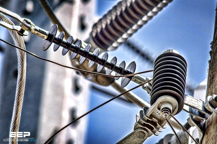 Power distribution configurations with three three-phase hot power lines (photo credit: Matt Alsup via Flickr)
The local electrical utility usually decides where the three-phase and single-phase services are to be located in the area that it serves.
The nominal 120/240 V power is obtained from transformers strategically located on poles for overhead service and above ground on concrete pads or in underground protective vaults for underground service.
Large electrical appliances such as ranges, water heaters, clothes dryers, and air conditioners typically require 240 V, while 120 V meets the needs for lighting, small appliances, TVs, personal computers, and convenience outlets.

However, when residences are located in an area served by a 208Y/120 V distributed secondary network, large appliances are powered by 208 V, but lighting, small appliances, entertainment electronics, and outlets are supplied with 120 V.
Common power service
Secondary circuits provide electrical power in various forms to satisfy customer demand. These include following:
- Single-phase, three-wire, 120/240 V
- Three-phase, four-wire, 120/208 V wye-connected
- Three-phase, four-wire 120/240 V delta-connected
Single-phase, three-wire, 120/240 V
The most common distribution wiring configuration for homes, small businesses, and farms is 120/240 V, single-phase service.

Figure 1 is a schematic diagram of a distribution transformer for 120/240 V single-phase service. The 240 V is obtained by making connections between the two ungrounded “hot” conductors, and the 120 V is obtained by making connections between either of the two “hot” ungrounded conductors and the neutral (grounded) conductor.
Three-phase, four-wire, 120/208 V wye-connected
Different voltages can be obtained with three-phase, four-wire, 120/208-V wye-connected service, as illustrated in Figure 2.

The terminal points of the three windings of a wye-connected transformer are designated A, B, and C. The voltage between any of the points A, B, and C and the neutral (grounded) conductor is 120 V, and the voltage between any two of the points A to B, B to C, or C to A is 208 V.
Therefore,the following voltages can be obtained from the wye-connected system:
- 120 V, single-phase, two-wire (A to neutral, B to neutral, and C to neutral)
- 208 V, single-phase, two-wire (A to B, B to C, and C to A)
- 208 V, three-phase, three-wire
- 120/208 V, three-phase, four-wire
Another popular wye-connected three-phase, four-wire system is rated at 277/489 V. Feeder and branch circuits connected to this supply can provide:
- 277 V, single phase, two-wire
- 480 V, single-phase, two-wire
- 480 V, three-phase, three-wire
- 277/480 V, three-phase, four-wire
Three-phase, four-wire 120/240 V delta-connected
A different set of output voltages can be obtained with the three-phase, four-wire delta-connected transformer secondary as shown in the schematic Figure 2.
The three windings are connected in series to form an equilateral triangle or Greek letter ∆. Each of the vertices of the triangle is designated by a letter, A, B, or C, representing one of the three phases that feed the network. The midpoint of the winding between vertices B and C is grounded at neutral point N.
The voltage between any two vertices A to B, B to C, and C to A is 240 V. However, the voltage between B and neutral and C and neutral is 120 V, while the voltage between A and neutral is 208 V.
Therefore, the following voltages can be obtained from the delta-connected system:
- 120 V, single-phase, two-wire (B to neutral and C to neutral)
- 240 V, single-phase, two-wire (A to B, B to C, and C to A)
- 240 V, three-phase, three-wire
- 120/208 V, three-phase, four-wire

Caution is required when making connections to a three-phase, four-wire trans- former secondary because of the potential damage that can be caused by accidentally connecting the “high-leg”. A to neutral voltage where the lower voltage is desired.
“On a 4-wire, delta-connected secondary where the midpoint of one phase winding is grounded to supply lighting and similar loads, the phase conductor having the higher voltage to ground shall be identified by an outer (insulation) finish that is orange in color or by tagging (or taping) or other effective means.”
The intent of this NEC precautionary requirement is prevent any connections from being made accidentally between A and ground and getting 208 V when the intent was to obtain 120 V from either B or C to ground. Thus the wire from A to ground would have orange insulation or be marked with orange tape or an orange tag.
Reference: Handbook of electrical design details // Second edition – Neil Sclater; John E. Traister (Purchase ebook)
Related electrical guides & articles


Edvard Csanyi
Hi, I'm an electrical engineer, programmer and founder of EEP - Electrical Engineering Portal. I worked twelve years at Schneider Electric in the position of technical support for low- and medium-voltage projects and the design of busbar trunking systems.I'm highly specialized in the design of LV/MV switchgear and low-voltage, high-power busbar trunking (<6300A) in substations, commercial buildings and industry facilities. I'm also a professional in AutoCAD programming.
Profile: Edvard Csanyi

I think there is a typo in this sentence “Another popular wye-connected three-phase, four-wire system is rated at 277/489 V”
^^^
Presume you meant to say 480 V.
You said “Power leaves the substation on three, three-phase “hot” power lines that are strung adjacent to highways or along local roads to points of use. All three phases share a single neutral line and have the same voltage, but they are 120 electrical degrees out of phase with each other.”
But what is the mechanism that we use to make the phases 120 degree out of phase ith each other. How is that Just by simply connecting in star and delta we are able to get that?
Is there any special circuitry that makes them out of phase with each other like using triacs or diacs etc.?
Priya, Most power is generated by rotating generators, steam, Hydro, etc. in 3 phase power there are three electrically separate magnetic pole winding sets. If these pole sets are physically located 120 degrees apart in the generators circle of rotation, then the resulting sinusoidal power in the three separate circuits will also be 120 degrees apart.
Parabenizo este artigo com todos os diagramas ou projeto de redes, gosto muito de sistema de potência.
I concure with Renee that figure 3 is wrong and misleading. As it is drawn A to C phase should be 240V and A to neutral is 208V.
i nned information of yours pulications
Greetings,
I request to know whether its possible to run a 240Vac 60Hz 3 phase motor on a single phase 50Hz 240Vac power supply by using a single phase to 3 phase variable speed drive.
It is not stated where (which country) this installation practice might apply – certainly NOT in Australia, and in particular where it implies that dual voltages are provided for domestic applications (High power, low power) which appears to be possibly quite a dangerous situation.
There is an error in Figure 3.
A 208 v potential is incorrectly labeled as 240.
Figure 3 is labelled correctly. The “wild” Leg of the delta 4 wire connection is 208 volt from the neutral to hot.