
Estimated Study Time: 12 minutes
Power distribution and LV switchgear
In designing a power distribution concept, encompassing the sizing of systems and devices, it is essential to align the requirements and feasibility with both the end user and the manufacturer. The appropriate sizing of low-voltage switchgear necessitates an understanding of its application, availability, and potential for future expansion. The requirements for power distribution are quite varied.
 Rules for power distribution in LV switchgear and protection of branch or distributed lines (photo credit: EEP - Electrical Engineering Portal)
They begin with buildings that impose minimal requirements on the power supply, such as office buildings, and progress to those with substantial demands, exemplified by data centers and industrial facilities, where uninterrupted operation is paramount.
For example, in designing a power distribution system for a manufacturing facility, it is essential to prioritize system availability, extensibility, control, and visualization to minimize plant downtimes.
Selectivity is crucial for a dependable power source. A significant variety of designs exists between these two extremes, which should be optimally aligned with customer specifications.
Design of a LV switchgear
Power distribution in low voltage switchgear can be defined as supplying power to a number of physically separate and individually protected circuits from a single circuit.
Depending on the circuits to be supplied, distribution will be via busbars (flat or C-section copper or aluminium bars), via prefabricated distribution blocks (power distribution blocks, modular distribution blocks, distribution terminal blocks) or via simple supply busbars.
Figure 1 – Main busbar at the top of the enclosure with 2 copper bars per pole
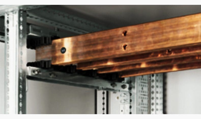
Figure 2 – Branch busbar in cable sleeve: C-section aluminium bars

According to the standards, a device providing protection against short circuits and overloads must be placed at the point where a change of cross-section, type, installation method or composition leads to a reduction in the current-carrying capacity (IEC 60364-4-43).
Figure 3 – Power distribution in LV switchgear

If it were applied to the letter, this rule would lead to over-sizing of cross-sections for fault conditions. The standard therefore allows for there to be no protection device at the origin of the branch line subject to two conditions.
There is no other tap-off or power socket on the branch line S2 upstream of protection P2.
Figure 4 – Upstream device P1 effectively protects the branch line S2

Theoretical layout
P1 protects S1 and P2 protects S2. There is no reduction in cross-section before P2.
Figure 5 – Theoretical layout

Multi-level distribution
This layout can be used for example when several distribution blocks (2nd level) are supplied from a single busbar (1st level). If the sum of the currents tapped off at the first level (I1, I2, etc.) is greater than It, a protection device P2 must be provided on S2.
Figure 6 – Multi-level power distribution

Modular power distribution block
Modular power distribution block mounted on DIN rail.
Figure 7 – Modular power distribution block mounted on DIN rail

Power distribution via supply busbars
Pin type comb busbars guarantee connection quality by eliminating the risk of short-circuits and ensuring a reliable connection via the top or bottom of the device. By limiting the short-circuit energy released in cables, service life of components in the installation is significantly extended.
Figure 8 – Legrand TX3 Pin type comb busbars

Conditions for protecting branch or distributed circuits
1. General principle for checking thermal stress
For insulated cables and conductors, the breaking time of any current resulting from a short circuit occurring at any point must not be longer than the time taken for the temperature of the conductors to reach their permissible limit.
This condition can be verified by: checking that the thermal stress K2S2 that the conductor can withstand is greater than the thermal stress (energy i2t) that the protection device allows to pass.
2. Checking the protection conditions of the branch line(s) with regard to the thermal stresses
For branch lines with smaller cross-sections (S2<S1), check that the stress permitted by the branch line is actually greater than the energy limited by the main device P1. The permissible thermal stress values K2S2 can be easily calculated using the k values given in the table below.
Table 1 – K values for conductors
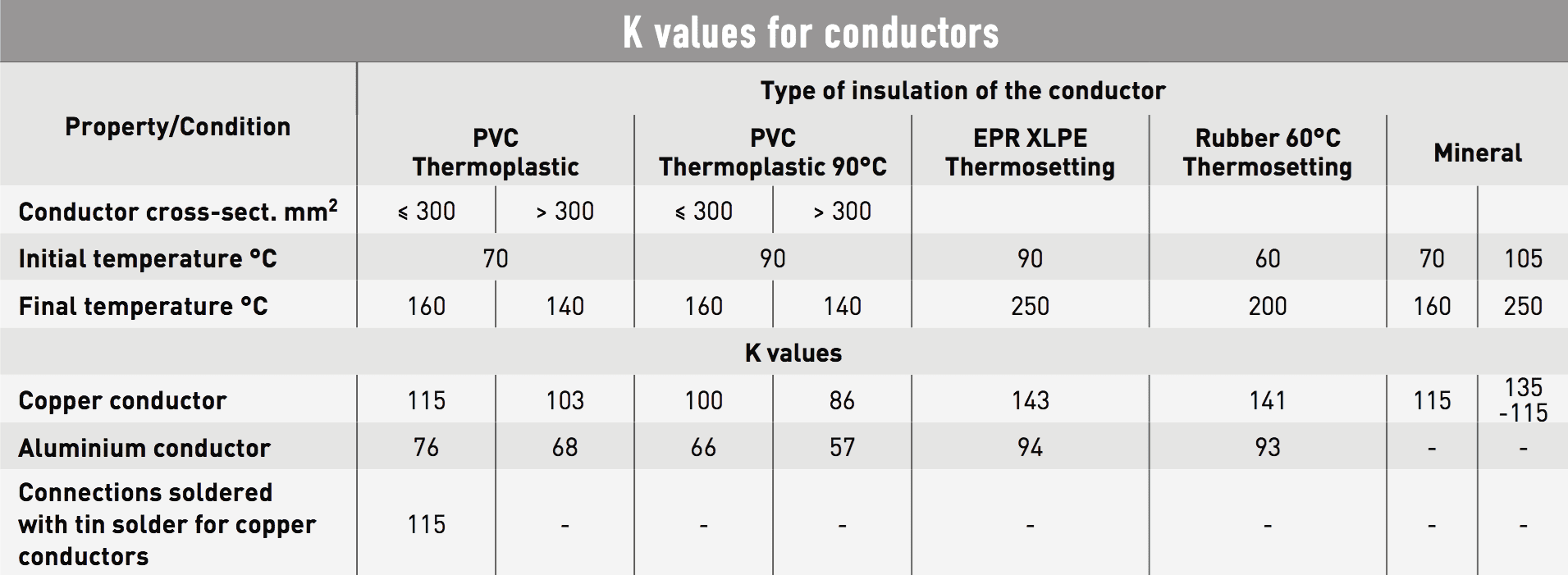
The maximum energy values limited by the devices are given in the form of figures (for example 55,000 A2s for modular devices with ratings up to 32 A or in the form of limitation curves).
3. Checking the protection conditions using the ‘TRIANGLE’ rule
The short-circuit protection device P1 placed at the origin a of the line can be considered to effectively protect branch S2 as long as the length of the branch busbar system S2 does not exceed a certain length, which can be calculated using the triangle rule.
- The maximum length L1 of the conductor with cross-section S1 corresponds to the portion of the circuit AB that is protected against short circuits by protection device P1 placed at point A.
- The maximum length L2 of the conductor with cross-section S2 corresponds to the portion of the circuit AM that is protected against short circuits by protection device P1 placed at point A.
Figure 9 – Triangle rule
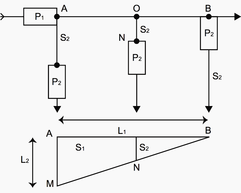
These maximum lengths correspond to the minimum short circuit for which protection device P1 can operate.
S1 corresponds to the cross-section of the main conductor and S2 to the cross-section of the branch conductor.
This method can be applied to short-circuit protection devices and those providing protection against overloads respectively, as long as device P2 effectively protects line S2 and there is no other tap-off between points A and O.
4. 3-metre rule applied to overload protection devices
When protection device P1 placed at the head of line, S1 does not have any overload protection function or its characteristics are not compatible with the overload protection of the branch line S2 (very long circuits, significant reduction in cross-section).
It is possible to move device P2 up to 3 m from the origin (O) of the tap-off as long as there is no tap-off or power socket on this portion of busbar system and the risk of short circuit, fire and injury is reduced to the minimum for this portion (use of reinforced insulation conductors, sheathing, separation from hot and damaging parts).
Figure 10 – 3-metre rule applied to overload protection devices

5. Exemption from protection against overloads
Figure 11 – Exemption from protection against overloads

The diagram above illustrates three examples of tap-offs (S1, S2, S3) where it is possible not to provide any overload protection or simply not to check whether this condition is met:
- Busbar system S2 is effectively protected against overloads by P1 and the busbar system does not have any tap-offs or power sockets upstream of P2
- Busbar system S3 is not likely to have overload currents traveling over it and the busbar system does not have any tap-offs or power sockets upstream of P3
- Busbar system S4 is intended for communication, control, signaling and similar type functions and the busbar system does not have any tap-offs or power sockets upstream of P4.
Reference: Busbars and distribution
Related electrical guides & articles


Edvard Csanyi
Hi, I'm an electrical engineer, programmer and founder of EEP - Electrical Engineering Portal. I worked twelve years at Schneider Electric in the position of technical support for low- and medium-voltage projects and the design of busbar trunking systems.I'm highly specialized in the design of LV/MV switchgear and low-voltage, high-power busbar trunking (<6300A) in substations, commercial buildings and industry facilities. I'm also a professional in AutoCAD programming.
Profile: Edvard Csanyi

To be care with power connection from all device of electrical
Nice explain
Hi Edvard,
We are a low voltage electrical panel boards assembling company in Sri Lanka. I am working as the General Manager for the company. When I have time, I read your articles that appears in the net, i found those are very useful. Further there are six electrical engineers are working with me. I would like to update our engineers with your knowledge and improve the quality of panel boards. We are following IEC 61439 guide lines, we use E Planner for our designs. How do we actively participate or join with you ?
Thanking you,
Praharsha Gangaboda
General Manager
Venora Lanka Power Panels (Pvt.) Ltd.
Export Processing Zone, Biyagama, Sri Lanka