
Estimated Study Time: 9 minutes
Power factor correction principle
Loads such as induction motors draw significant reactive power from the supply system, and a poor overall power factor may result. The flow of reactive power increases the voltage-drops through series reactances such as transformers and reactors, it uses up some of the current carrying capacity of power system plant and it increases the resistive losses in the power system.
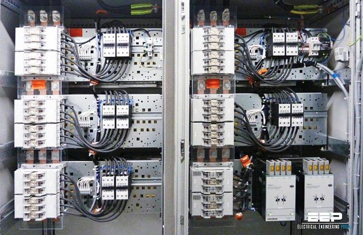 Tips for power factor correction and good protection of capacitors (on photo: PFC and capacitors protection; credit: janitza.com)
To offset the losses and restrictions in plant capacity they incur and to assist with voltage regulation, Utilities usually apply tariff penalties to large industrial or commercial customers for running their plant at excessively low power factor.
The basis for compensation is illustrated in Figure 1, where ∠ϕ1 represents the uncorrected power factor angle and ∠ϕ2 the angle relating to the desired power factor, after correction.
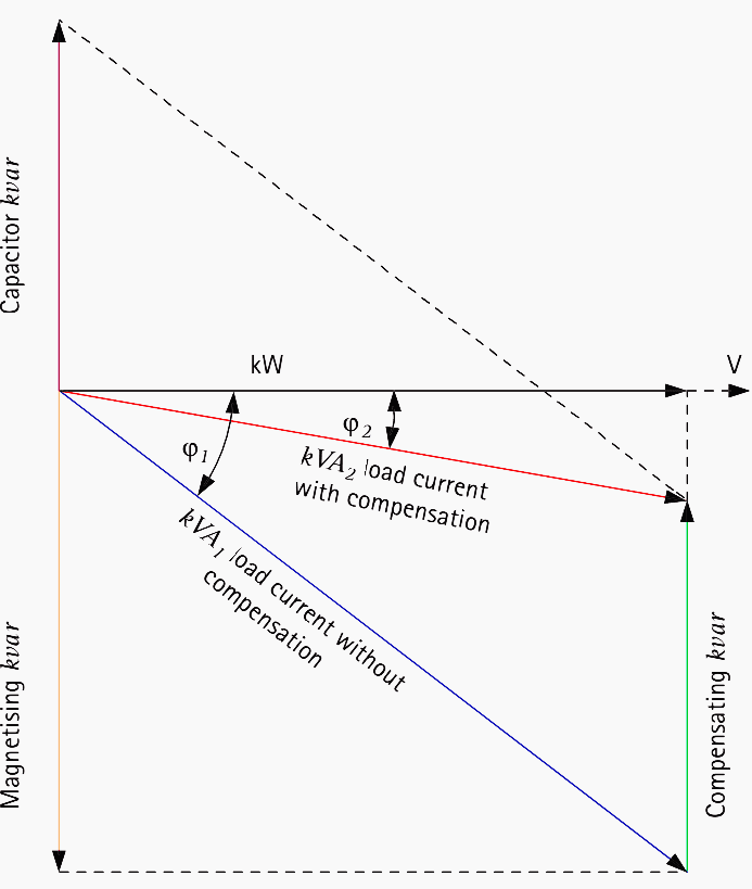
The following may be deduced from this vector diagram:
Uncorrected power factor = kW / kWA1 = cos∠ϕ1
Corrected power factor = kW / kWA2 = cos∠ϕ2
Reduction in kVA = kVA1 − kVA2
Capacitor kVAr = kW × (tan cos∠ϕ1 − tan cos∠ϕ2)
A spreadsheet can easily be constructed to calculate the required amount of compensation to achieve a desired power factor.
Capacitor Control
Where the plant load or the plant power factor varies considerably, it is necessary to control the power factor correction, since over-correction will result in excessive system voltage and unnecessary losses.
In a few industrial systems, capacitors are switched in manually when required, but automatic controllers are standard practice.
A controller provides automatic power factor correction, by comparing the running power factor with the target value.
Based on the available groupings, an appropriate amount of capacitance is switched in or out to maintain an optimum average power factor. The controller is fitted with a ’loss of voltage’ relay element to ensure that all selected capacitors are disconnected instantaneously if there is a supply voltage interruption.
When the supply voltage is restored, the capacitors are reconnected progressively as the plant starts up. To ensure that capacitor groups degrade at roughly the same rate, the controller usually rotates selection or randomly selects groups of the same size in order to even out the connected time.
The provision of overvoltage protection to trip the capacitor bank is also desirable in some applications. This would be to prevent a severe system overvoltage if the power factor correction (PFC) controller fails to take fast corrective action.
The design of PFC installations must recognise that many industrial loads generate harmonic voltages, with the result that the PFC capacitors may sink significant harmonic currents. A harmonic study may be necessary to determine the capacitor thermal ratings or whether series filters are required.
Motor Power Factor Correction
When dealing with power factor correction of motor loads, group correction is not always the most economical method. Some industrial consumers apply capacitors to selected motor substations rather than applying all of the correction at the main incoming substation busbars.
In some instances, better motor starting may also result, from the improvement in the voltage regulation due to the capacitor. Motor capacitors are often six-terminal units, and a capacitor may be conveniently connected directly across each motor phase winding.
Capacitor sizing is important, such that a leading power factor does not occur under any load condition. If excess capacitance is applied to a motor, it may be possible for self-excitation to occur when the motor is switched off or suffers a supply failure. This can result in the production of a high voltage or in mechanical damage if there is a sudden restoration of supply.
Since most star/delta or auto-transformer starters other than the ‘Korndorffer’ types involve a transitional break in supply, it is generally recommended that the capacitor rating should not exceed 85% of the motor magnetising reactive power.
Capacitor Protection
When considering protection for capacitors, allowance should be made for the transient inrush current occurring on switch-on, since this can reach peak values of around 20 times normal current. Switchgear for use with capacitors is usually de-rated considerably to allow for this. Inrush currents may be limited by a resistor in series with each capacitor or bank of capacitors.
Protection equipment is required to prevent rupture of the capacitor due to an internal fault and also to protect the cables and associated equipment from damage in case of a capacitor failure.
If fuse protection is contemplated for a three-phase capacitor, HRC fuses should be employed with a current rating of not less than 1.5 times the rated capacitor current.
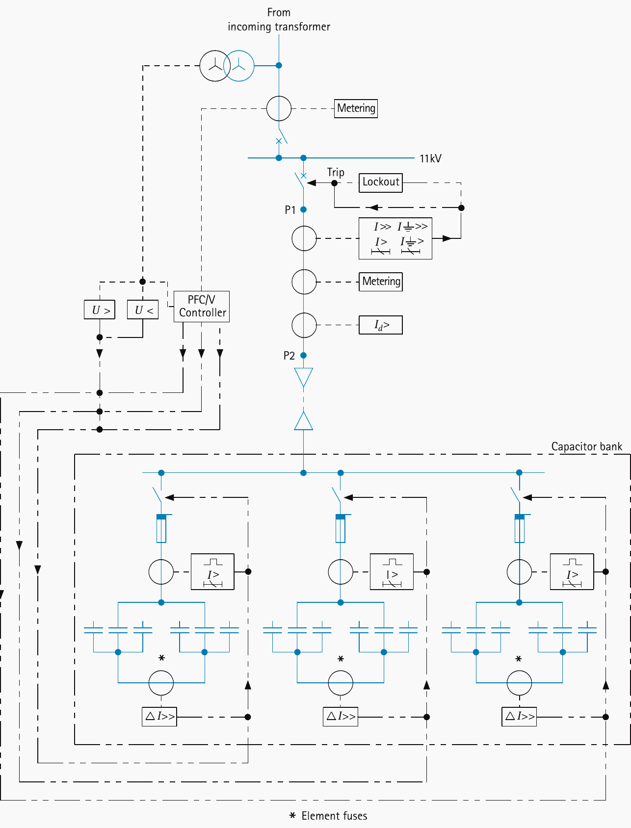
Medium voltage capacitor banks can be protected by the scheme shown in Figure 2 above. Since harmonics increase capacitor current, the relay will respond more correctly if it does not have in-built tuning for harmonic rejection.
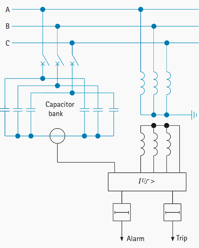
As shown in Figure 3, a current transformer in the inter star-point connection can be used to drive a protection relay to detect the out-of-balance currents that will flow when capacitor elements become short circuited or open-circuited.
The relay will have adjustable current settings, and it might contain a bias circuit, fed from an external voltage transformer, that can be adjusted to compensate for steady-state spill current in the inter star-point connection.
Some industrial loads such as arc furnaces involve large inductive components and correction is often applied using very large high voltage capacitors in various configurations.
Another high voltage capacitor configuration is the ‘split phase’ arrangement where the elements making up each phase of the capacitor are split into two parallel paths.
Reference // Network protection and automation guide by General Electric (ex Alstom)
Related electrical guides & articles


Edvard Csanyi
Hi, I'm an electrical engineer, programmer and founder of EEP - Electrical Engineering Portal. I worked twelve years at Schneider Electric in the position of technical support for low- and medium-voltage projects and the design of busbar trunking systems.I'm highly specialized in the design of LV/MV switchgear and low-voltage, high-power busbar trunking (<6300A) in substations, commercial buildings and industry facilities. I'm also a professional in AutoCAD programming.
Profile: Edvard Csanyi

Thanks for the useful article. In today’s scenario, the Harmonics play an important role. Usage of Detuned Reactors with the capacitors (for its protection and control of Harmonic enhancement) seems mandatory in today’s time.
Suggestion to add it this important topic too.
I do agree with you Edvard you take good care
Regards a friend Johhann
RC protection of the contactors are needed. This is available by a special plug-in module from
many manufacturers. Otherwise the contactor will eventually burnout. The film show this used
but does not mention it. Also, overvoltage (MOV) or combination GDT+MOV can be used.
This will save many hours of useful capacitor lifetime, because they do deteriorate!
Hello Edvard – thanks for this article. Could you please tell how to determine the values of capacitors that has to placed for different values of inductive loads?
Hi, What is the real formula for calculating the need of how much capacitor bank APFC panel to deisgn of how many steps if I have the total plant load and general pf?
Hi Edward, I tend to agree with Ryno Verster, the Capacitor KVAR / Compensating KVAR has to be (KVAR 1-KVAR 2)=KW(tan(phi_1)-tan(phi_2))
Great post Edvard, thank you! Looking forward to future installments.
Is Motor Power Factor Correction cost effective for consumer machines with electrical motors, like washers and dryers?
Thanks!
Hi Edvard – thanks for the article, good one. However I saw you refer to the Capacitor kVAR equation = kW (tan cos (phi_1) – tan cos (phi_2)). Shouldn’t it rather be = kW (tan (phi_1) – tan (phi_2)) without the cos terms?
Edvert Csanyi thanks a lot.
Hi Edvard,
Thank you for your effort in putting these all together. Can you advice about the power factor correction with Distributed Generation such as PV solar.