
Estimated Study Time: 7 minutes
Electrical system on board
Without going into the details of the management modalities of the electric distribution or of the layout that an electrical system on board may have, it is possible to describe it in short, however giving the possibility to understand its structure and complexity.
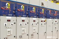
 LV/MV Distribution In Power Plants On Board Of Big Ships (photo credit: motorship.com)
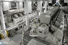
In the power plants on board of big ships, or however in the most modern ships, such as for example line cruisers, the generation of electric energy occurs in the power station on board, which, in some cases, can be divided into two parts, one placed astern and the other at the bow.
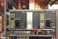
Medium voltage distribution (see Figure 1 below) starts from the main switchboard which consists of two sections, each of them connected to one gen-set.
These bars are usually connected through a bus-tie which allows the power to be handled according to the specific needs, always with the point of view of keeping, even if reduced, such an efficiency that a good degree of safety and stability is ensured for the ship.
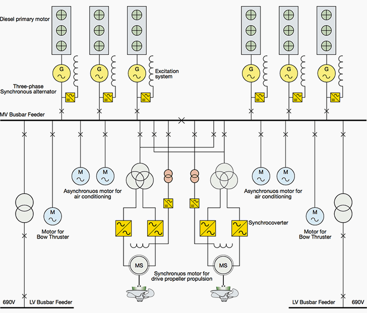
The medium voltage main busbar system or some distribution sub-switchboards deliver power, directly or through control devices (e.g. electronic converters) to:
- Essential high power loads (e.g. the propellers or the thrusters for transverse motion);
- Big power motors, for example for air-conditioning or for the typical functions linked to particular vessel typology;
- Various substations in the service areas intended to supply LV power to all the power loads, small power loads or lights provided for that area.
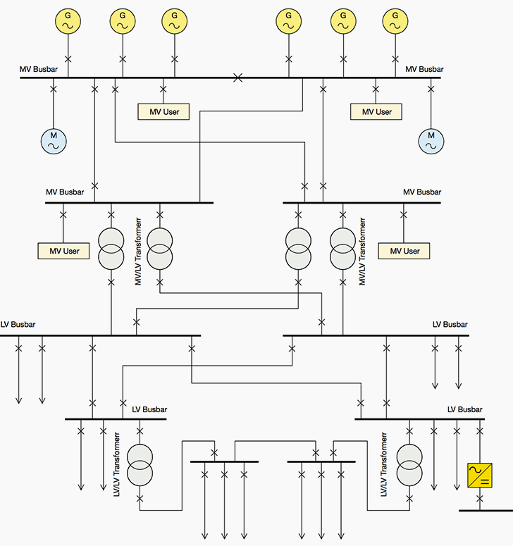
Therefore, the secondary power supply of the LV switchboards starts from the substations, through MV/ LV transformers. These switchboards often offer the possibility of having redundant supply coming from other MV switchboards supplied in turn by the other half-busbar of the main MV switchboard.
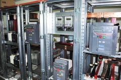
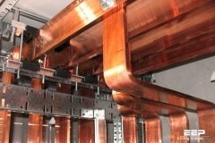
From the LV switchboards a complex distribution network (see Figure 2) is originated and it supplies the different types of LV loads on board, such as the rudder, the winches or the essential auxiliaries of the motor and, moreover, the lightning plant, the entertaining, comfort and performance facilities, as well as the accommodation structures with kitchens and laundries.
The power plant must always guarantee service continuity; therefore, switchboards with two incoming feeders de- riving from other separate switchboards are provided.
In case of fault, putting out of service, as fast as possible, only the load involved or the section affected by the breakdown is important, thus realizing high selectivity for all the loads.
In the previous paragraph, the MV generation voltage values have already been mentioned. Instead, as regards the distribution levels of the LV plant, till some years ago the standard value was 440V.
This has implied some advantages, such as:
- Partial reduction of the fault current values,
- Reduction of the cross sectional areas of the cables and consequently of weights and overall dimensions,
- Reduction of voltage drops and bigger admissible lengths of cables and an increase in the power of the motors which can be directly connected to the primary network and generally of all the loads of the Main Switchboard.
Low voltage final distribution is carried out at lower voltages (400V/230V), obtained through LV/LV transformers. The frequencies most commonly used are 50Hz or 60Hz according to different aspects, such as for example the type of naval construction and the country of origin.
For special loads, or more simply in the military eld, dedicated circuits are required in the presence of 400Hz.
Typically, the direct current has voltage values of 48V, 110V or 125V are maintained for those particular circuits, for example, where devices for battery recharging or for automation auxiliary circuits are provided.
Redundant supply //
As already said, also the lack of supply for the fundamental utilities must be avoided for safety on board. Therefore the distribution system shall provide for the possibility of a redundant supply.
For example dividing the MV main busbar, which closes if needed, so that the power supply to the electric propulsion engines is ensured in order not to jeopardize the ship maneuver-ability, or for LV switchboards to provide the possibility of a double supply deriving from other switchboards, or also through adequate designing of the emergency power station.
Electrical power plants on board are typically in alternating current since they result to guarantee a better management in terms of costs and reliability in comparison with direct current ones.
Will be continued soon…
Reference // Generalities on naval systems and installations on board – ABB
Related electrical guides & articles


Edvard Csanyi
Hi, I'm an electrical engineer, programmer and founder of EEP - Electrical Engineering Portal. I worked twelve years at Schneider Electric in the position of technical support for low- and medium-voltage projects and the design of busbar trunking systems.I'm highly specialized in the design of LV/MV switchgear and low-voltage, high-power busbar trunking (<6300A) in substations, commercial buildings and industry facilities. I'm also a professional in AutoCAD programming.
Profile: Edvard Csanyi

I PREFER MV RING MAIN DESIGN ON SHIP
Nicely written article.
There are various factors and basically the type of vessel , it’s industrial Mission and also the Class Notation(Intended/Assigned) decides the modalities/architecture of the power plant onboard ships.
Rarely you will find Power plant split in Forward and Stern. There are vessels which has physically segregated (also maintaining Fire and Flood Integrity) power plants but not in Forward and Astern.
Do you have single line diagram for the Ship’s electrical system with symbol meaning? Thanks