MV primary distribution network
The MV primary distribution network generally consists in a three-phase system with three conductors without neutral. Such system is usually managed with the neutral of the star point isolated from earth or connected with earth through a resistance or a Petersen coil, thus allowing a reduction in the values of leakage and short-circuit currents.

Continued from the first part Power plants on board of big ships – LV/MV ditribution
In this way, a first fault with insulation loss does not represent a hazard and allows the system to be maintained in service without the intervention of the protection.
Obviously the fault must be signaled and standard service conditions must be immediately restored so that it can be avoided that the first fault turns into a double fault to earth, which is extremely dangerous in IT systems.
Once, when onboard installations were not very wide and the powers involved quite small, the secondary distribution system consisted in a single-phase network with two insulated conductors or three conductors with the medium point of the transformer connected to earth.
Generally, the secondary distribution network is radially distributed with the possibility of double switchboard supply through two different lines, thus realizing the reserve connection to the load. The choice of using one type or the other depends on the plant conditions and it is carried out either by means of a switch or of interlocked circuit-breakers.
- Radial power distribution
- Compound radial distribution
- Power distribution with ring circuit
- High-Voltage Shore Connection (HVSC)
Radial power distribution
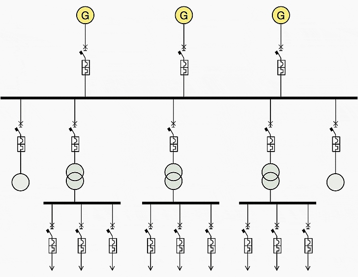
MV main distribution networks have a different structure according to the type of ship and to the installed power. They can be of simple radial type with substations or sub-switchboards.
The simple radial diagram (see Figure 1) includes a main switchboard with a single busbar, from which the output feeders for all the LV power consumers start. This con guration results to be particularly critical since a fault on the main switchboard may jeopardize the reliability of the services on board.


Compound radial distribution
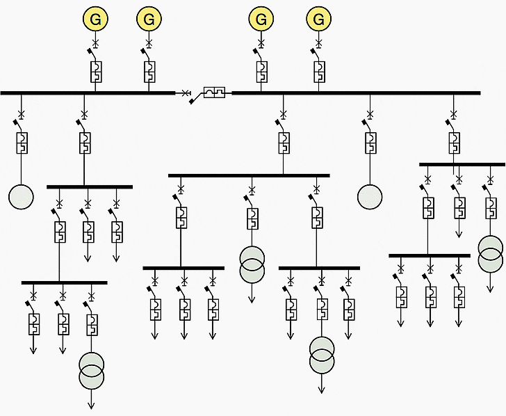
The compound radial diagram (see Figure 2) is fitter than the previous one for the realization of medium power plants and comprises a main switchboard with one or more main busbars and some sub-switchboards, which provide solely for the power supply delivery from the main switchboard to the distribution switchboards differently placed.
With this configuration there is a remarkable reduction in the number of the circuits derived from the main switchboard and therefore of the devices installed in the switchboard.


Instead, as regards the service continuity of the users derived from different distribution sub-switchboards, a remarkable importance is represented by the correct sizing of the chain of circuit-breakers positioned at the different levels of the distribution system so that it is possible to obtain the tripping of the circuit-breaker affected by the fault only, thus guaranteeing power supply for the other loads and sub-switchboards.
Power distribution with ring circuit
To ensure power supply continuity, the radial system is often structured with a reserve ring (Figure 3) intended for the supply of the substations having the main line interrupted, or even the whole substation group in case of a serious fault on the semi-busbar of the main switch- board usually supplying them.
In this case, which is to be considered very heavy and hard, only half the generators results to be available and consequently half the energy power installed. The ring shall be sized to provide for the needs of the plant foreseen for this operation situation, which, as it is evident, is of extreme emergency.


The plant on board may be divided into three main parts, represented by:
1. Main plant
The main plant, consisting of the essential services of the ship, such as the propulsion or the circuits intended for priority functions on board, each of them characteristic of the ship typology (e.g. the circuits intended for gas pumping or compression for a gas carrier, or the circuits intend for the control of the devices for load handling on shipping containers).
2. Auxiliary circuits //
The auxiliary circuits which include power production and distribution systems for lightening and auxiliary motive force;
3. Special installations //
The special installations for which a particular technology has been developed:
- Telephone installations,
- Electronics devices for different uses,
- Telegraphs,
- Torquemeters,
- Integrated navigation systems,
- Fire warning devices.
Another main difference concerns the distinction which can be made between essential and non-essential loads, which influence the distribution system which supplies them.
The first ones are those for which supply and proper operation are to be guaranteed also under emergency conditions, since they carry out functions indispensable to the safety of the vessel. Among them, first of all the propulsion system, the control systems of motors, helms and stabilizer paddles, the re-prevention systems, the alarms, the communication and auxiliary systems for navigation, the emergency lightening.
The electrical system, in compliance with the Naval Regisisters’ rules, provide also an emergency electrical station positioned in another area with respect to the power station on board, usually on one of the high decks and however over the waterline. The power station consists of an autonomous LV diesel-generator set (440V or 690V), in the order of some MW.
The diesel engine under consideration shall be able to start also when the main network cannot deliver energy and this is usually obtained by means of a connection to the UPS system. A set of capacitors is present to guarantee energy availability also during the starting time of the emergency generator. Under standard operating conditions, that is in the presence of voltage on the mains, a rectifier shall have the task of delivering to the capacitor banks the energy necessary to keep the maximum charge.
In case of malfunctioning of the main station, an automatic control sequence provides for switching to the emergency switchboard the power delivery of the part of the plant to which the priority loads, which must work also in emergency case, are connected (e.g. emergency lightning, re pumps, steering devices and auxiliary equipment indispensable for the machinery systems, communication and signaling networks and other circuits).
High-Voltage Shore Connection (HVSC)
Besides, due to environmental constraints, in harbors ships must turn their diesel engines off thus interrupting electric generation. Then they must connect to the on-shore grid, normally to a LV source, or in the most modern solutions to a MV tap made available in the port.
This procedure, defined High-Voltage Shore Connection (HVSC) finds favor with the harbor management authorities worldwide, allows for a reduction in the polluting emissions of ships at berth, improving air quality in the port areas and in the surrounding ones.


HVSC technology (Figure 4) allows power supply directly from the wharf to the vessel to ensure operation of the machinery systems and installations on board (refrigerators, illumination, heating and air-conditioning) and allow the diesel engines normally used to supply electrical generators on board to be turned off.
This operation in parallel, which is necessary for onboard electrical power supply must not cause problems of power quality to the onshore distribution grid.
To give an idea of the environmental impact, a big line cruiser at berth for 10 hours, if using onshore power supply, avoids burning of up to 20 metric tons of fuel, which is equivalent to 60 metric tons of carbon dioxide not emitted into the atmosphere, which is the annual emission of 25 cars.


Reference // Generalities on naval systems and installations on board – ABB


Continue advancing with more installation techniques for substations in big ships.
Good day,
Can anyone tell me the legal minimum distance a 6.3KV Junction box can be mounted from a handrail outside on a main deck area
please give me a highlight of how hydroelectricity can be generated using a marine vessel propulsion system. if possible e-mail me the response.
Thanks
Very useful information, thanks
Hello Edvard Csanyi,
You are doing a remarkable job by running this portal. Please continue to do so.
It has become my favourate reading.
I have become your fan.
Best Regards
Rakesh Sharma
Sydney
0404978992
Symbology should be in accordance with IEC standards.
I assume that instead of “lightening” it should be “LIGHTING”.
Regrettably the concepts explained in the article are not different from the concepts of standard power systems for any type of use.
Agree about terminology, but why ‘regrettably’? It’s what it is :)