
Estimated Study Time: 16 minutes
Sizing the power quality problems
Nowadays everybody speaks about power quality. For many reasons, I would say. Electrical energy is now polluted more than ever, and consumers are more sensitive to power disruptions and fluctuations than a small flower to the stronger wind. But, it is as it is. It’s up to us to do something about all this. There are many levels of implementation of power quality in commercial plants.
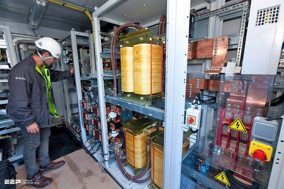 Five power quality devices that every commercial plant must have installed (photo credit: nicegrid.fr)
Many plants have some power quality solutions implemented, but how many of them have done an in-depth analysis of their electrical system and the actual need for power? The point is that power quality analysis is a smart job, and it costs a lot.
However, the most important is that the size of power quality problems must be defined by estimating the cost of disruptions caused to distribution system equipment (utilities and consumers’ equipment) and the extent of its sensitivity to power quality. Some plant equipment may be less sensitive to disturbances, allowing it to ride through the disturbances.
In that case there is no need to apply a solution.
The power quality devices are used to protect the electrical equipment or to eliminate the source of disturbances or to mitigate the effect of disturbances.
The devices that are commonly used for this application include the following: surge protection device, shielding, uninterruptible power supply, dynamic voltage restorers, series capacitors, capacitor voltage transformers, wiring and grounding, static var compensator, energy storage system (ESS), backup generators, isolation transformers and filters.
Examples of Power Quality Devices
Electrical equipment with microprocessor-based controls and power electronic devices that are sensitive to disturbances are affected by poor power quality. Control systems can be affected by momentary voltage sag or small transient voltages, resulting in nuisance tripping of processes.
Furthermore, many of these sensitive loads are interconnected in extensive network and automated processes. This interconnected nature makes the whole system dependent on the most sensitive device when a disturbance occurs.
Let’s see these five devices that can improve the power quality:
- Surge protection devices
- Backup generators
- Uninterruptible power supply (UPS)
- Isolation transformer
- Voltage regulators (stabilizers)
1. Surge protection devices
The electrical equipment in distribution systems may be exposed to internal or external surges. Internal surges are generated within a facility by users’ equipment. They result from switching processes, for example, switching inductive or capacitive loads, fuse or breaker opening in an inductive circuit.
External surges are generated outside a facility and enter the facility through utility wires. They result from fuse operation, power system switching and lightning.
Surge protection devices protect the equipment against these surges by limiting the amount of undesired surge energy that reaches the equipment. The surge energy is diverted to a path rather than the equipment itself (neutral or earth).
Then the majority of surge energy is directed through surge protection device, and most of this energy is dissipated in its internal resistance (Figure 2).
2. Backup generators
In large industries and for long-duration interruptions, backup generation is essential to supply at least the critical loads. It is common to use diesel generators set with rating sufficient for feeding these critical loads such as emergency lighting system, electric lifts, industrial processes that cannot withstand long interruption, hospitals and the like.
Usually, the backup generator is used as a standby unit and connected to the distribution system of industry at the main low voltage switchboard (see Figure 3). An automatic transfer switch (ATS) can be used to automatically transfer the power source from the utility incoming feeder to the backup generator in emergency cases.
An electrical interlock is provided between both sources to avoid parallel operation.
Some of the outgoing feeders of non-essential loads may be disconnected to keep the power demand within the generator rating that is mostly less than the rating of the utility source.
In many cases, the main LV busbar is sectionalized into two sections with a bus coupler to increase the reliability. Each section is fed from a different utility source (see Figure 4). The outgoing feeders of critical loads are preferred to be connected to one of these two sections that is supplied by the utility source in normal operation and backup generator in emergency operation.
The circuit breakers A, B, C and D must be controlled to satisfy the truth table given in Table 1. This table indicates on/off positions of generator circuit breaker D at different combinations of breakers A, B and C positions. Position “on” is represented by “1,” while “0” represents “off
position”.
Table 1 – Circuit breakers positions ‘0’ for Off and ‘1’ for On
| A | B | C | D |
| 0 | 0 | 0 | 1 |
| 0 | 0 | 1 | 0 |
| 0 | 1 | 0 | 1 |
| 0 | 1 | 1 | 0 |
| 1 | 0 | 0 | 1 |
| 1 | 0 | 1 | 0 |
| 1 | 1 | 0 | 1 |
| 1 | 1 | 1 | 0 |
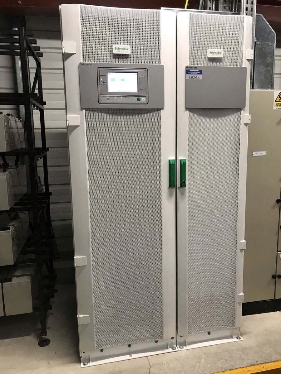
3. Uninterruptible power supply (UPS)
The UPS is an alternative power source to supply power to the load during interruption or outage of main power source (e.g., utility source). The UPS includes a rectifier circuit to convert AC input power into direct current (DC) power. The DC power charges a set of batteries to store energy and an inverter to convert the DC stored energy back onto AC power for the load (see Figure 5).
A 6- or 12- or 24-diode bridge can constitute the rectifier circuit depending on the desired level of wave distortion. From the point of view of frequency stability as well as voltage stability, the inverter that constitutes the UPS generator has performance superior to that of the mains.
It is designed to generate sinusoidal voltage even when supplying nonlinear loads, that is, dealing with highly distorted currents.
For instance, in a single-phase unit with half-bridge converter, the square wave voltage appearing between A and B (see Figure 6) is filtered so as to obtain in the output of the unit a sinusoidal voltage wave.
During normal operation, the utility supplies power both to the load directly bypassing the UPS unit and to the UPS to charge its batteries via the rectifier circuit. In emergency operation, for instance an outage of utility power source, the UPS supplies power to the load fast enough (few milliseconds) to avoid any damage resulting from load interruption.
This necessitates using an electronic transfer switch to change the power source to load.
UPSs are effective for digital electronics-based loads, such as computer systems and PLCs where the loss of data is avoided. On the other hand, they have deficiencies where the transfer switch and rectifier are exposed to line disturbances in normal operating conditions. In an emergency, the operation time of UPS is limited by the capacity of batteries.
The design of UPSs and, generally, ESS depends on the required mode of operation. Three modes of operation are considered: standby (offline), online and line interactive. (Learn more about UPS devices)
The standby mode of operation means that the ESS operates only during the interruption time, while it operates full time in the case of online mode of operation. Line-interactive mode of operation includes both of these two modes.
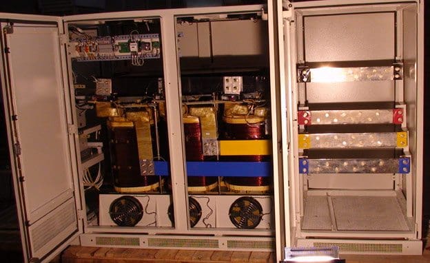
4. Isolation transformer
They are generally composed of two separate windings with a magnetic shield between these windings to offer noise control. The noise can be transported to the electric device by electromagnetic coupling (EMC) in two basic ways: a differential mode noise and a common mode noise (see Figure 8).
The isolation transformer is connected between the power source and the electric device. Therefore, it carries the full load current and thus must be suitably sized.
The main benefit offered by isolation transformers is the isolation between two circuits by converting electrical energy to magnetic energy and back to electrical energy, thus acting as a new power source.
4.1 How does isolation transformer work?
Considering a high voltage, high current transient is introduced into a power line by the direct and indirect (induced) effects of lightning activity or a switching surge.
If these transients are differential mode, then the isolation transformer will effectively pass these transients with little or no attenuation.
If, on the other hand, these transients are common mode, then a suitable shielded isolation transformer will provide effective protection against such surges. This is because a common-mode transient is split in two between a pair of power lines, and they proceed in the same direction. They flow into the transformer from its terminals and run in the primary coil, finally going out to the earth through the shield plate.
At this moment, they run in the coil in opposite directions, canceling their inductive effects in the secondary side. Therefore, a common-mode transient does not reach the secondary side (see Figure 9).
It can thus be seen that the shielded transformer will provide effective protection against common-mode surges provided the peak voltage does not exceed the insulation rating of the transformer. It also effectively provides no attenuation of differential mode surges.
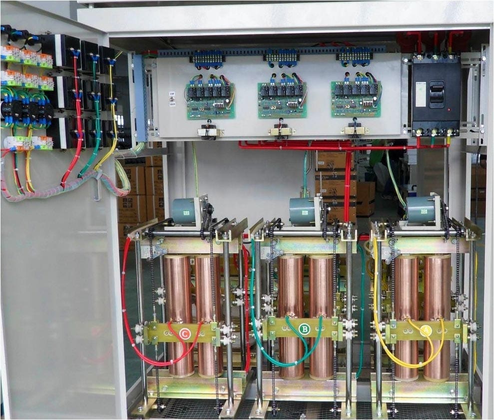
5. Voltage Regulators
The function of voltage regulators is to maintain the voltage at load within preset limits. During voltage sags voltage regulators increase the voltage to a desired level for sensitive loads and, conversely, during overvoltages or swells they decrease the voltage. Mostly, the usage of voltage regulators is to mitigate the effect of sag events.
The common type used for regulating the voltage is a motor-driven variable-ratio autotransformer. A motor is used to change the location of a slider on transformer winding, providing a change of transformer ratio to increase or decrease the voltage levels (see Figure 11).
The response time is slow, which may be inadequate for some loads and may not correct large short-term voltage variations.
Servo voltage stabilizer (it works on servomechanism) uses a servo motor to enable the voltage correction. It is mainly used for high output voltage accuracy, typically ±1 percent with input voltage changes up to ±50 percent.
Internal circuit of a servo stabilizer incorporates servo motor, autotransformer, buck boost transformer, motor driver and control circuitry.
Sources:
- Electric distribution systems by ABDELHAY A. SALLAM and OM P. MALIK
- Protection against lightning effects by Legrand
Related electrical guides & articles


Edvard Csanyi
Hi, I'm an electrical engineer, programmer and founder of EEP - Electrical Engineering Portal. I worked twelve years at Schneider Electric in the position of technical support for low- and medium-voltage projects and the design of busbar trunking systems.I'm highly specialized in the design of LV/MV switchgear and low-voltage, high-power busbar trunking (<6300A) in substations, commercial buildings and industry facilities. I'm also a professional in AutoCAD programming.
Profile: Edvard Csanyi

Great stuff, very informative! I work for Dranetz, we are the originators of commercial PQ instruments. We just released a brand new PQ instrument in January.
Hi,
I do want to know more about diversity factor in power distribution system.