
Estimated Study Time: 8 minutes
Dynamic Reactive Power Compensation
In many cases, industrial plants are characterized in particular by the use of highly dynamic drive technology. In addition to the undeniable advantages of these modern technologies, there is the disadvantage that the electrical networks are strained because of frequent changes in load and harmonics.
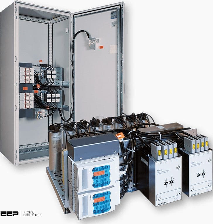 Improvement of Power Quality via Dynamic Reactive Power Compensation Systems (photo credit: Janitza)
This causes unstable voltage conditions, flickering, excessive current loads and increased loss in the electrical power distribution. This in turn not only reduces the usable network power, but also affects the functions of sensitive electronic controllers.
Conventional power factor correction systems are designed for the pure optimization of the power factor and also to reduce the harmonics level, but are not able to keep up with fast load changes and do not provide a satisfactory solution.
The application area of these systems is the compensation of static or slowly changing loads with switching cycles in the range of minutes.
Another positive effect of the dynamic reactive power system is the ‘soft’ switching of the capacitors.
Conventional equipment with air contactors creates transient inrush currents which not only affect the compensation components, but can also lead to damage and perturbations (or distortions) of consumers. The real-time power factor compensation equipment generally switches on and off during zero current crossing, so avoiding transient interference completely.
Furthermore, brief voltage fluctuations and the related flickering of the bulb in lamps are increasingly becoming problems for electrical power technology. In other words, voltage fluctuations can cause light current changes in an incandescent lamp. Flicker is the subjective impression of changes in lighting density.
How to improve power quality?
The demand for a dynamic reactive power compensation system today is actually the desire for high-speed control. Effective access to the power conditions within fractions of a network cycle is only possible when powerful semiconductor components are used.
The fact that ‘reactions’ are possible with power semiconductors within a network cycle increases the application area of a dynamic reactive power compensation system to include also voltage stabilization or ‘power quality support’ (i.e. during strong effective power surges, the energy stored in the power capacitors can be switched through within just a few milliseconds to support the power quality).
The fundamental frequency power factor (basic harmonic reactive power factor cos φ1) is in the middle here, at about 0.7.
With modern machines, the amount of welding current is usually set by thyristors so that the following network perturbations occur for line-commutated converters:
- Harmonic currents due to non-sinusoidal network currents. Network voltage drops.
- Particularly in networks with relatively low short-circuit power, the network perturbations increase.
For the sake of completeness, it should be mentioned here that voltage drops are also a cause of flicker.
With dynamic real-time compensation, a combination of high-speed controller and thyristor power modules is substituted for the conventional components (reactive power controller and capacitor contactor).
This system reacts with a minimal delay of one network cycle to a change in load and thus prevents rapid change in reactive power in the electrical network. The fundamental frequency power factor (basic harmonic reactive power factor cos φ1) is optimized at all times and the network load is reduced to a minimum.
To eliminate the reaction time totally, control of the compensation steps can be performed directly by the controller electronics of large single consumers.
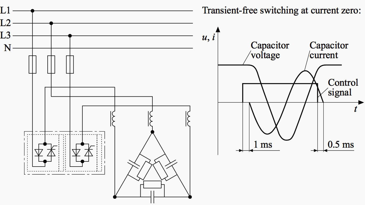
Figure 1 above shows the principle of a dynamic reactive power compensation system with thyristors. Thyristors are suitable for switching capacitive loads (i.e. reactor-protected capacitors and capacitors without reactors).
The functioning principle, as can be seen from Figure 1, is as follows:
The device consists of two thyristor modules which switch phase conductors L1 and L3. The phase conductor L2 is not switched. Single-phase operation is also possible for the thyristor modules. If the ‘ON’ signal is applied to the control input of the thyristor, the integrated control electronics switches the thyristors to the next negative current zero crossing separately for each phase conductor. Switching off also takes place during current zero crossing.
This principle eliminates transient switching disturbances (transient effects) and network perturbations.
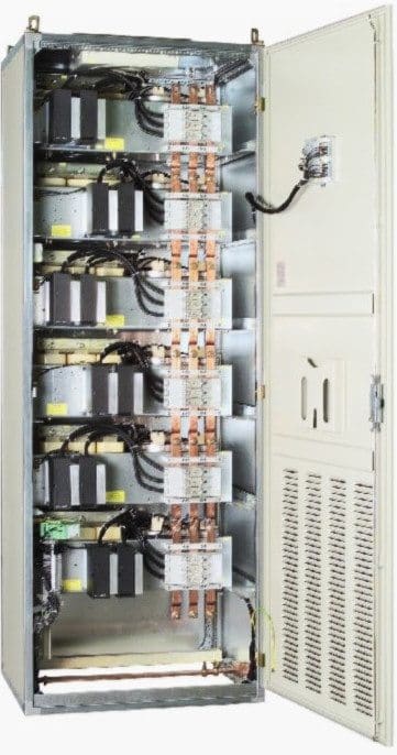
Thyristor power modules showed in (Figure 2) can be used together with:
- Programmable logic controllers (PLCs).
- Reactive power controllers or process controllers.
- Computer systems or process engineering.
And particularly for:
- High-speed switching.
- Without network perturbations due to transient-free switching during current zero crossing.
Examples of typical applications are the following:
- Cranes.
- Elevators.
- Spot welding machines (primary pulsed).
- Sensitive production processes (e.g. the semiconductor industry).
Some of the advantages of dynamic reactive power compensation are listed below:
- Improvement of the power quality.
- Increase in available power (i.e. improved power network utilization).
- Decrease in transmission losses.
The advantages of switching with thyristors are:
- No high switch-on currents. Transient-free switching.
- Switching within one sinusoidal half cycle.
- Unlimited number of switching operations.
- Avoidance of drops in voltage.
Reference // Reavtive power compensation by Wolfgang Hofmann, Jurgen Schlabbach and Wolfgang Just (Purchase hardcover from Amazon)
Related electrical guides & articles


Edvard Csanyi
Hi, I'm an electrical engineer, programmer and founder of EEP - Electrical Engineering Portal. I worked twelve years at Schneider Electric in the position of technical support for low- and medium-voltage projects and the design of busbar trunking systems.I'm highly specialized in the design of LV/MV switchgear and low-voltage, high-power busbar trunking (<6300A) in substations, commercial buildings and industry facilities. I'm also a professional in AutoCAD programming.
Profile: Edvard Csanyi
