Power quality problems
Many power quality problems are caused by inadequate wiring or improper grounding. These problems can be detected by simple examination of the wiring and grounding systems. Another large population of power quality problems can be solved by spot-checks of voltage, current, or harmonics using hand held meters.

Longer-term power quality monitoring
Some problems, however, are intermittent and require longer-term monitoring for solution.
Long-term power quality monitoring is largely a problem of data management. If an RMS value of voltage and current is recorded each electrical cycle, for a three-phase system, about 6 gigabytes of data will be produced each day. Some equipment is disrupted by changes in the voltage waveshape that may not affect the rms value of the waveform.
Recording the voltage and current waveforms will result in about 132 gigabytes of data per day.
Most commercially available power quality monitoring equipment attempts to reduce the recorded data to manageable levels. Each manufacturer has a generally proprietary data reduction algorithm. It is critical that the user understand the algorithm used in order to properly interpret the results.
Selecting a Monitoring Point
Power quality monitoring is usually done to either solve an existing power quality problem, or to determine the electrical environment prior to installing new sensitive equipment. For new equipment, it is easy to argue that the monitoring equipment should be installed at the point nearest the point of connection of the new equipment.
For power quality problems affecting existing equipment, there is frequently pressure to determine if the problem is being caused by some external source, i.e., the utility. This leads to the installation of monitoring equipment at the service point to try to detect the source of the problem.
This is usually not the optimum location for monitoring equipment.
Most studies suggest that 80% of power quality problems originate within the facility. A monitor installed on the equipment being affected will detect problems originating within the facility, as well as problems originating on the utility.
Each type of event has distinguishing characteristics to assist the engineer in correctly identifying the source of the disturbance.
What to Monitor?
At minimum, the input voltage to the affected equipment should be monitored. If the equipment is single phase, the monitored voltage should include at least the line-to-neutral voltage and the neutral- to-ground voltages. If possible, the line-to-ground voltage should also be monitored. For three-phase equipment, the voltages may either be monitored line to neutral, or line to line.
Line-to-neutral voltages are easier to understand, but most three-phase equipment operates on line-to-line voltages. Usually, it is preferable to monitor the voltage line to line for three-phase equipment.
If the monitoring equipment has voltage thresholds which can be adjusted, the thresholds should be set to match the sensitive equipment voltage requirements. If the requirements are not known, a good starting point is usually the nominal equipment voltage plus or minus 10%.
In most sensitive equipment, the connection to the source is a rectifier, and the critical voltages are DC. In some cases, it may be necessary to monitor the critical DC voltages. Some commercial power quality monitors are capable of monitoring AC and DC simultaneously, while others are AC only.
It is frequently useful to monitor current as well as voltage. For example, if the problem is being caused by voltage sags, the reaction of the current during the sag can help determine the source of the sag. If the current doubles when the voltage sags 10%, then the cause of the sag is on the load side of the current monitor point.
If the current increases or decreases 10–20% during a 10% voltage sag, then the cause of the sag is on the source side of the current monitoring point.
It can also be useful to record power quantity data while searching for power quality problems. For example, the author found a shortcut to the source of a disturbance affecting a wide area by using the power quantity data. The recordings revealed an increase in demand of 2500 KW immediately after the disturbance. Asking a few questions quickly led to a nearby plant with a 2500 KW switched load that was found to be malfunctioning.
Selecting a Monitor
Commercially available monitors fall into two basic categories: line disturbance analyzers and voltage recorders. The line between the categories is becoming blurred as new models are developed.
Voltage recorders are primarily designed to record voltage and current stripchart data, but some models are able to capture waveforms under certain circumstances.


Line disturbance analyzers are designed to capture voltage events that may affect sensitive equipment. Generally, line disturbance analyzers are not good voltage recorders, but newer models are better than previous designs at recording voltage stripcharts.
In order to select the best monitor for the job, it is necessary to have an idea of the type of disturbance to be recorded, and an idea of the operating characteristics of the available disturbance analyzers.


Nuisance tripping of variable speed drives
For example, a common power quality problem is nuisance tripping of variable speed drives.
Variable speed drives may trip due to the waveform disturbance created by power factor correction capacitor switching, or due to high or low steady state voltage, or, in some cases, due to excessive voltage imbalance. If the drive trips due to high voltage or waveform disturbances, the drive diagnostics will usually indicate an overvoltage code as the cause of the trip.
If the voltage is not balanced, the drive will draw significantly unbalanced currents. The current imbalance may reach a level that causes the drive to trip for input overcurrent.
Selecting a monitor for variable speed drive tripping can be a challenge. Most line disturbance analyzers can easily capture the waveshape disturbance of capacitor switching, but they are not good voltage recorders, and may not do a good job of reporting high steady state voltage.
Many line disturbance analyzers cannot capture voltage unbalance at all, nor will they respond to current events unless there is a corresponding voltage event. Most voltage and current recorders can easily capture the high steady state voltage that leads to a drive trip, but they may not capture the capacitor switching waveshape disturbance.
Many voltage recorders can capture voltage imbalance, current imbalance, and some of them will trigger a capture of voltage and current during a current event, such as the drive tripping off.
To select the best monitor for the job, it is necessary to understand the characteristics of the available monitors.
[bt]
RMS voltage delivered to the equipment
The most commonly recorded parameter in power quality investigations is the RMS voltage delivered to the equipment. Manufacturers of recording equipment use a variety of techniques to reduce the volume of the data recorded. The most common method of data reduction is to record Min/Max/Average data over some interval.
This is a simple, easily understood recording method, and it is easily implemented by the manufacturer.
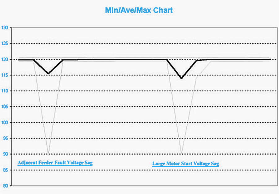
There are several drawbacks to this method. If there are several events during a recording interval, only the event with the largest deviation is recorded. Unless the recorder records the event in some other manner, there is no time-stamp associated with the events, and no duration available.
The most critical deficiency is the lack of a voltage profile during the event. The voltage profile provides significant clues to the source of the event.
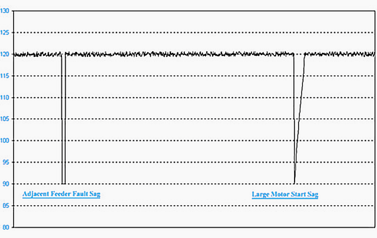
For example, if the event is a voltage sag, the minimum voltage may be the same for an event caused by a distant fault on the utility system, and for a nearby large motor start. For the distant fault, however, the voltage will sag nearly instantaneously, stay at a fairly constant level for 3–10 cycles, and almost instantly recover to full voltage, or possibly a slightly higher voltage if the faulted section of the utility system is separated. For a nearby motor start, the voltage will drop nearly instantaneously, and almost immediately begin a gradual recovery over 30–180 cycles to a voltage some- what lower than before.


Figure 3 shows a cycle-by-cycle recording of a simulated adjacent feeder fault, followed by a simulation of a voltage sag caused by a large motor start.
Figure 4 shows a Min/Max/Average recording of the same two events. The events look quite similar when captured by the Min/Max/Average recorder, while the cycle-by-cycle recorder reveals the difference in the voltage recovery profile.


Reference // Power quality monitoring by Patrick Coleman


Very interesting article.
Power Quality analysis is every day more challenging for professionals and identifying exactly where to measure can be very tricky and requires time, that’s absolutely true.
Multipoint wireless portable Power Quality analyzers like NanoVIP QUADRA system are a powerfull solution to ease the analysis, avoiding attempts and shrinking times.
This system offers remote realtime monitoring, synchronous campaigns and the possibility to include non electrical parameters too; at least, part of real problems discussed in this article are then overtaken.