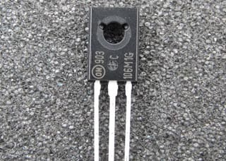
The thyristor, also called a silicon-controlled rectifier (SCR), is basically a four-layer three-junction pnpn device. It has three terminals: anode, cathode, and gate. The device is turned on by applying a short pulse across the gate and cathode. Once the device turns on, the gate loses its control to turn off the device.
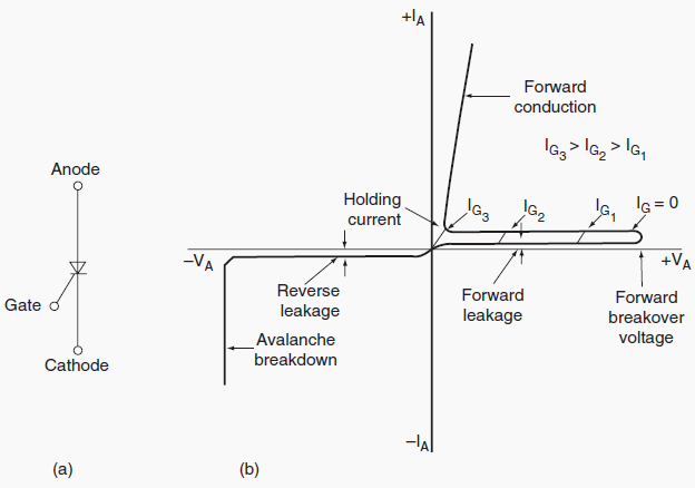
The turn-off is achieved by applying a reverse voltage across the anode and cathode. The thyristor symbol and its volt-ampere characteristics are shown in Figure 1. There are basically two classifications of thyristors: converter grade and inverter grade. The difference between a converter-grade and an inverter-grade thyristor is the low turn-off time (on the order of a few microseconds) for the latter.
The converter-grade thyristors are slow type and are used in natural commutation (or phase-controlled) applications. Inverter-grade thyristors are used in forced commutation applications such as DC-DC choppers and DC-AC inverters. The inverter-grade thyristors are turned off by forcing the current to zero using an external commutation circuit.
This requires additional commutating components, thus resulting in additional losses in the inverter.
Thyristors are highly rugged devices in terms of transient currents, di/dt, and dv/dt capability. The forward voltage drop in thyristors is about 1.5 to 2 V, and even at higher currents of the order of 1000 A, it seldom exceeds 3 V.
While the forward voltage determines the on-state power loss of the device at any given current, the switching power loss becomes a dominating factor affecting the device junction temperature at high operating frequencies. Because of this, the maximum switching frequencies possible using thyristors are limited in comparison with other power devices considered in this section.
Thyristors have I2t withstand capability and can be protected by fuses. The nonrepetitive surge current capability for thyristors is about 10 times their rated root mean square (rms) current. They must be protected by snubber networks for dv/dt and di/dt effects. If the specified dv/dt is exceeded, thyristors may start conducting without applying a gate pulse. In DC-to-AC conversion applications, it is necessary to use an antiparallel diode of similar rating across each main thyristor.
Thyristors are available up to 6000 V, 3500 A.
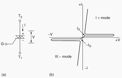
A triac is functionally a pair of converter-grade thyristors connected in antiparallel. The triac symbol and volt-ampere characteristics are shown in Figure 2. Because of the integration, the triac has poor reapplied dv/dt, poor gate current sensitivity at turn-on, and longer turn-off time.
Triacs are mainly used in phase control applications such as in AC regulators for lighting and fan control and in solid-state AC relays.
SOURCE: Kaushik Rajashekara – Delphi Automotive Systems







Dear Edvard, i would like to ask if i can get a full document stating how external pulse commutation is done
thank you
I like it for my study.
IThe Thirystor high current and high voltage aplicattions (2000A 2500V) they includes in the same silicon block a antiparalell diode for protectintion inverse voltage and redriving the current for turn off them. In medium aplications the fast fuse employs for protections are called “Protistor” in serial.
Hi Sally,
There are two ways of driving TRIAC’s without isolation depending on triac used. One is using quadrants II and III and is most common as most of the triacs are not capable of running in quadrant IV, and the second is using quadrants I and IV.
Dear Edvard,
Thanks for info about SCR & Traic introduction. I would like to ask a question.
usually, How to determine Traic triggering in which quadrant if I deign it for dimmer lamp application?
Sally