
Estimated Study Time: 31 minutes
Substation requirements
The space requirements of a power substation depend on the equipment to be housed, and on whether a new building can be erected for it or it has to be fitted into an existing building. In the case of an existing building, it may be difficult to achieve an ideal solution, but where no severe limitations have been imposed there are layouts that would prove satisfactory.
 Power substation equipment and wiring essentials
Figure 1 is an example layout. This layout is suitable for a main 11 kV substation, also supplying local low-voltage distribution, and it will be seen that it meets most of the following requirements:
Requirement №1 – There is adequate clearance around the equipment and space to withdraw circuit-breakers for maintenance.
Requirement №2 – Equipment operating at different voltages is segregated (advisable but not mandatory).
Requirement №3 – There is sufficient space for drawing in and connecting cables, and for the delivery and erection of additional switchgear: doorways are high and wide enough.
Requirement №4 – The walls can act as fire barriers. If a high-voltage bus-section switch is included, a decision must be made as to the need for fire barrier walls between the sections. Even with oil circuit-breakers, this risk is small and many engineers disregard it.
Requirement №5 – Transformers are usually housed in open or semi-open compounds; but if an indoor location is essential, particular attention must be paid to its ventilation.
The risk of a transformer fire is extremely small: nevertheless, an oil sump (usually filled with pebbles) should be provided to trap burning oil which could escape following a fire.
Over the past 20 years, the concept of package substations was introduced whereby cast-resin transformers, low-voltage switchgear, automatic power factor correction equipment and 11 kV switchgear is incorporated into a composite arrangement. It should be realized that there are savings in installation costs with possible improvements in safety.
Figure 1 – Typical 11/0.415 kV substation layout
Today it is not unusual to find commercial buildings with electrical loads totalling tens of megawatts. The recent explosion of the IT industry and internet technologies have seen electrical loads in these bespoke buildings of up to 400 megawatts. The traditional approach of locating the transformers in the basement or in an outdoor compound with 415 V cabling to the low-voltage switchboards may result in a very expensive distribution system.
This same approach can be as readily applied to industrial buildings.
To simplify the stock of spares and to ensure ready interchangeability between gear in different substations, as much standard equipment as possible should be used, even at the expense of varying from the ideal installation. In general, substations should be limited to a capacity of about 2000 or 3000 kVA, with individual transformers no larger than 1500 kVA, to allow for the use of commercial low-voltage switchgear of about 43 kA rupturing capacity.
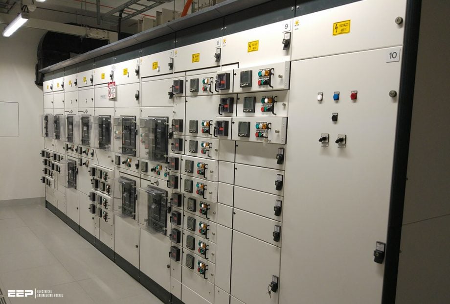
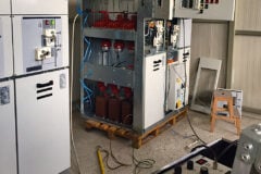
Figure 2 – 415 V switchboard, incorporating main incoming LV air circuit-breaker and outgoing LV circuits
- Compact substations
- Low-voltage distribution
- Medium voltage switchgear and protection systems
- Wiring systems
- Distribution transformers
1. Compact substations
In addition to the substation designs previously referred to, the so-called ‘compact substation‘ or ‘packaged substation‘ has become increasingly popular. A typical design incorporates a high-voltage SF6 switch, a cast resin transformer and fused low-voltage outgoing ways. They are popular with supply authorities partly because of their com pact construction, which makes them attractive for installation where space is at a premium.
They also require a minimum of site erection work, which can be a significant factor in some situations.
They can be supplied complete with a prefabricated enclosure, often of moulded reinforced fibreglass construction, or unclad and suitable for direct installation in a building.
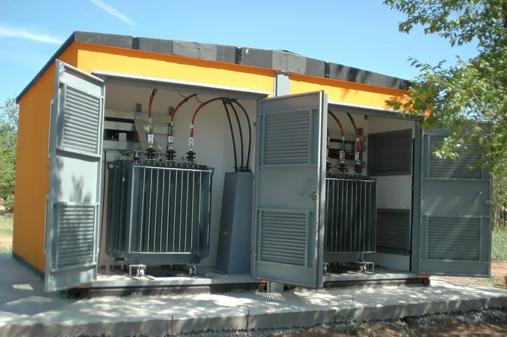
Figure 3 – Compact substation with two transformers 10/0.4 kV 1250kVA installed
Go back to the Contents Table ↑
2. Low-voltage distribution
At substations, the low-voltage distribution switchgear consist usually of a circuit-breaker for each transformer with circuit-breakers or switches and fuses for the outgoing feeders. Low-voltage feeders are usually supplied with ammeters and often with meters to measure the energy consumption of the feeder.
In many cases, maximum-demand meters are included so that this feature can be periodically monitored – a useful facility in large industrial complexes. Intelligent low-voltage switchgear is now available where strategically placed voltage sensors and circuit telemetry is monitored by a PLC.
Thermal monitoring of busbars and connections using continuous infra-red detectors are also available. This feature is very important is some critical applications
With duplicate cables, one may be entirely spare or both cables may share the load, provided that they are both of sufficient capacity to carry the total current independently in an emergency.
Figure 4 – Single-line diagram of modernized load-centre power distribution system where 480V load-centre unit substation and 2400V master unit substations replace old large low-voltage substations.
From the substations described above, low-voltage feeders run to subsidiary substations or load centres. These can include multi-motor starter boards, air-conditioning control boards, lighting and heating power distribution boards, vertical or horizontal busbars, street lighting supplies, etc.
The range of alternatives is wide and the following paragraphs outline only some of the solutions available.
Go back to the Contents Table ↑
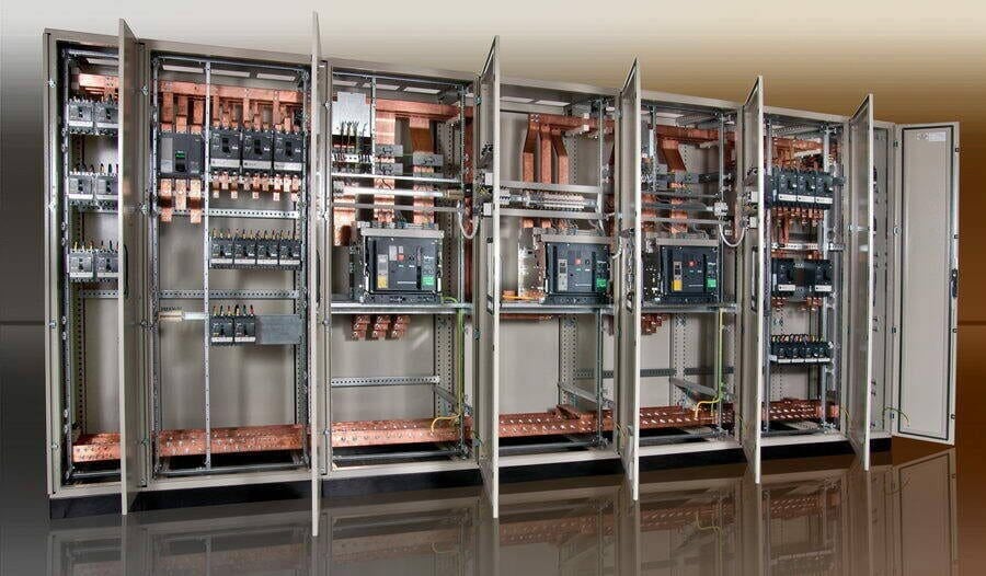
2.1 Main distribution board (MDB)
Main distribution board (MDB) is a panel or enclosure that houses the fuses, circuit breakers and ground leakage protection units where the electrical energy, which is used to distribute electrical power to numerous individual circuits or consumer points, is taken in from the transformer or an upstream panel.
MDB typically has a single or multiple incoming power sources and includes main circuit breakers and residual current or earth leakage protection devices. A MDB is comprised of a free standing enclosure, a bus bar system, MCCB’s (molded case circuit breaker), metering and support equipment and required current transformers.
Main distribution boards are used to distribute and control the power supply in large buildings such as shopping malls, hospitals, universities, and hotels. The main distribution boards are generally installed after the main power source (eg. Transformers or generators) and the main idea of MDB is to divide the power supply into secondary outgoing feeders.
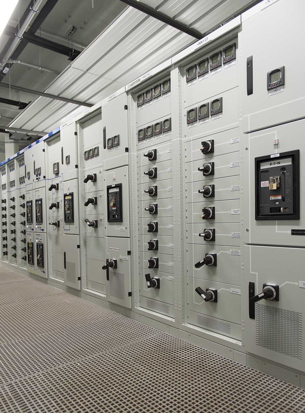
Figure 5 – Main distribution board (MDB)
Main distribution board typically consists of the following components:
- Busbar Section,
- Moulded Case Circuit Breakers (MCCB),
- Air Type Circuit Breakers (ACB),
- Current Transformers (CTs),
- Voltage transformers (VTs),
- Electric Counter,
- Multimeter,
- Power logic,
- etc.
Go back to the Contents Table ↑
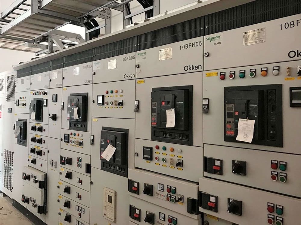
2.2 Motor control centre (MCC)
Large motors are usually supplied with independently separate feeders. The motor control centre will probably have a facility for intelligent motor protection. This is advisable because of the heavy fluctuating load, which might otherwise cause disturbance to other plants on the same supply.
However, where a number of small or medium-sized motors are in reasonable proximity, it is convenient to group the starters in a motor control centre panel, which often includes one or more distribution boards for lighting.
Figure 6 – Low voltage Motor control centre (MCC) type OKKEN
Motor control centre (MCC) typically consists of the following components:
- Contactors,
- Motor protection switches (depends on choice),
- Thermal overload relays (depends on choice),
- Frequency converter starter (depends on choice),
- Soft starter (depends on choice),
- Star-delta timer,
- Miniature circuit breakers,
- Thermal-magnetic circuit breakers,
- Residual current circuit breakers,
- Time relay,
- 24V AC transformer (220/24V),
- Auxiliary relays,
- etc.
Go back to the Contents Table ↑
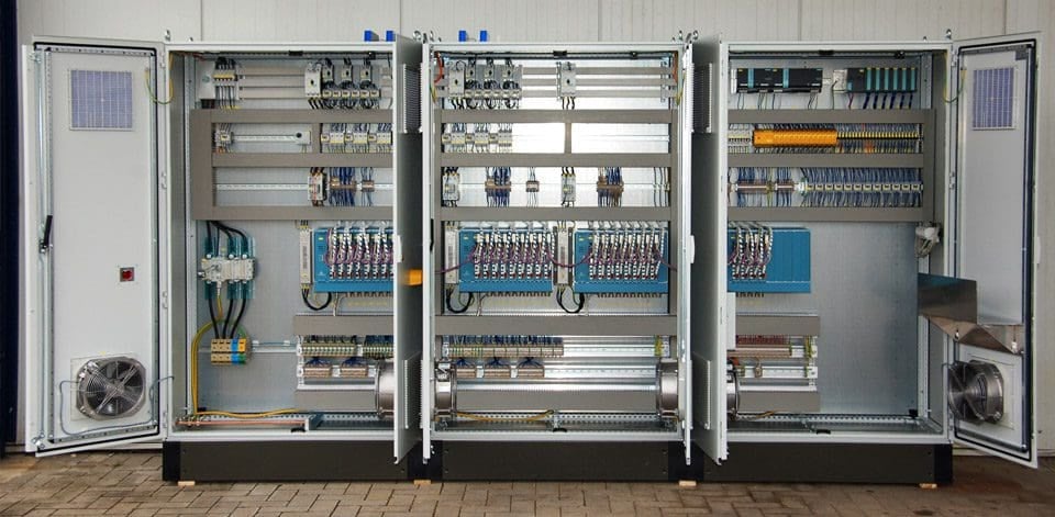
2.3 Air conditioning and ventilation control boards
These are variants of the multi-motor starter board. As well as starters for the fans and pumps of the system, they also include the specialist control equipment needed for the automatic control of the air conditioning and ventilation.
Similar developments are found in many industries where plant process-control equipment is incorporated into a combined motor starter and small-power boards. These starter boards may also incorporate equipment for Building Management systems (BMS) and communications capability to connect onto circuit breakers and MCCBs which allows diagnostic data, indication signals and energy management to take place.
Intelligent motor control can be incorporated to monitor overload, overheating and earth faults.
Figure 7 – Control and automation cabinet for ventilation and air conditioning
Go back to the Contents Table ↑
2.4 Busbar systems
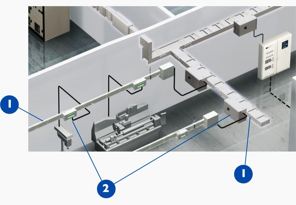
In general, wherever there are continuous rows of machine tools to be fed, an overhead busbar system provides the required degree of flexibility. Used vertically, a busbar system offers the simple and flexible provision of power in a high-rise building. There are many manufacturers that offer copper/aluminium busbars, embedded in epoxy cast resin, enclosed in steel trunking and provided with tapping points at intervals.
Standard, as well as custom-sized tees, elbows, bends and other accessories, are available. At the tapping points, it is possible to insert a tapping box, which can be safely applied or removed with the internal busbars live. When positions of machines have to be changed or new machines installed, it is easy to insert a tapping box at the appropriate point in the run of the busbar trunking.
Fire barriers are required for vertical runs, and for long runs, it is advisable to provide busbar expansion joints.
Figure 8 – Typical distribution busbar trunking layout
From the individual fuse switch (or circuit-breaker) units on the overhead busbar, cables in conduit or flexible metallic tubing are run to the machine tools. In the case of tools with more than one motor, distribution switchboards can be mounted at a convenient point on the equipment.
Vertical busbars are usually run in a vertical duct within the building. A lock-proof cupboard is formed at each floor level and the distribution boards and switches are accommodated therein, with the outgoing supplies fed to meet the lighting and power needs of the floor occupants.
Where possible, it is preferable to use only one phase on each floor of the building, as this eliminates the risk of voltages in excess of 240 V being encountered by personnel.
Suggested Course – Learn How to Depict Switchgear and Substation Single-Line Diagrams
Learn How to Depict Switchgear and Substation Single-Line Diagrams
Go back to the Contents Table ↑
3. Medium voltage switchgear and protection systems
The series MV metal enclosed cells are designed with the purpose of use medium voltage switchgear (control) in secondary distribution systems up to 36 kV, compact kiosk type substations and industrial buildings.
All functional units that may be required in power substation can be established easily side by side. Production at the factory has been completed and all routine and type tests made cubicles can be activated in a practical way in a very short time using it safely.
Modular cubicles typically consists of four main sections:
- Cable connection and switching section
- The main busbar section
- Part of the operating mechanism
- Low voltage section
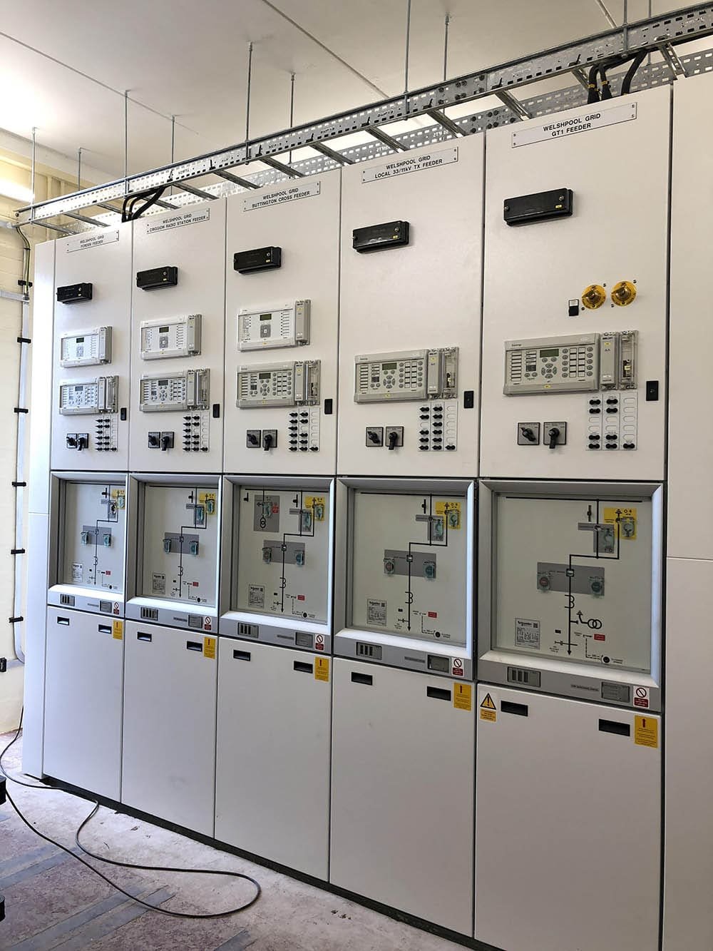
Figure 9 – Medium voltage switchgear (Schneider Electric)
Go back to the Contents Table ↑
4. Wiring systems
The choice of wiring system for industrial, commercial and domestic installations depends on the structure, application, supply voltage, load, appearance and cost. An essential feature is a proper earthing system giving an earth continuity conducting path for protection and safety.
Go back to the Contents Table ↑
4.1 Steel conduit
A screwed steel conduit, either galvanised for corrosion resistance or black enamel, provides a potentially good earth continuity and makes it possible to enclose cables throughout their length with strong mechanical protection. The conduit is normally of a heavy-gauge welded construction.
Skill is required to achieve a proper system of good appearance. The conduit should be erected completely before cables are drawn in; tube ends should be reamered to prevent damage to cables; draw-in boxes should be amply proportioned and accessible; the conduit should be adequately supported by saddles or clips.
Most conduit systems in factories are run on the surface, but in offices, or where conduit would be affected by corrosive fumes, it may be sunk in concrete in the floor or in walls behind plaster or cement. The layout must be carefully preplanned, and joints must be tight, to prevent the ingress of wet concrete, cement or plaster.
A draw wire should be pulled through as soon as possible after pouring or plastering, to remove any intrusive material before it hardens. The actual wiring is left until all is dry, and all wiring in one conduit must be drawn in at the same time.
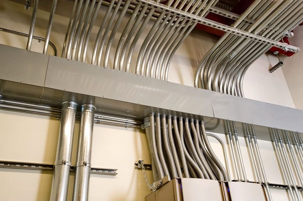
Figure 10 – Cables installation through steel conduits
Go back to the Contents Table ↑
4.2 Plastic conduit
In recent years there has been an upsurge in the use of plastic conduit. Polyvinyl chloride (PVC) components are generally unaffected by water, acids, oxidising agents, oils, aggressive soils, fungi and bacteria, and they can be buried in concrete or plaster. They provide slight resistance to heat and flame, and in this respect are inferior to steel conduit. Their mechanical strength is also much less.
A flexible heavy-duty nylon conduit is also available for cable protection in installation systems. This system is self-extinguishing, free of phosphor, halogen and cadmium and is shock resistant. They are not electrically conductive and separate earth continuity conductors have to be run, which on occasion can require a larger diameter than for a steel conduit.
PVC conduit and fittings are marginally cheaper than the equivalent steel conduit components, but PVC is a by-product of the oil industry and its price comparison with steel conduit is likely to vary.
Suggested Video – PVC Conduit and trunking installation practical work
Go back to the Contents Table ↑
4.3 Trunking
Trunking is used to bunch numbers of cables or wires which follow the same route, with branches to motors, switchgear and lighting circuits by spurs in trunking or conduit. Trunking is made in various sections from 50 mm ( 50 mm upward and in standard lengths. Tees, reducers, crossings, elbows and other fittings.
Both steel and plastic trunking is used. With the former, low-resistance joints between lengths of trunking and fittings are essential. If the trunking is itself used as a ‘protective conductor’ under the requirements of the Wiring Regulation, its bonding and jointing are specified.
On a switchboard or distribution panel in which lengths of trunking enclose the various interconnecting cables, the units should be bonded to the trunking by copper earth tape. In the case of vertical runs of trunking, internal fire barriers must be fitted at each floor level. These barriers must also be fitted in horizontal runs where the trunking passes from one zone of fire protection to another.
Suggested Reading – Four very important precautions for the installation of cables and busbar trunking systems
Four very important precautions for the installation of cables and busbar trunking systems
Plastics trunking is made in sizes similar to those for steel trunking, small sizes being extruded and large ones formed from PVC laminated sheets. Common fittings are available, but as PVC is easily ‘formed’, special fittings can be ‘welded’ with the help of a hot-air welding gun. The characteristics of PVC trunking makes it particularly suitable for fume-laden atmospheres, humid tropical conditions and salt-laden coastal air.
The material has the physical characteristics mentioned in the previous section ‘Plastic conduit’ and for the same reason requires a copper conductor to be included to provide effective earth. Screwed or snap covers may be used.
Go back to the Contents Table ↑
4.4 Cabling
The following cables have applications special to the wiring of buildings:
4.4.1 Mineral insulated metal sheathed cables (MIMS)
A mineral insulated metal sheathed (MIMS) cable normally consists of high-conductivity single-strand copper conductors inside a seamless copper sheath packed with magnesium-oxide powder as the insulant. As an alternative aluminium conductor and sheath are also available. The sheath acts as a robust and malleable conduit, capable of withstanding considerable mechanical abuse.
Although dearer than the equivalent steel conduit installation, there are applications where mineral insulated metal sheath (MIMS) cabling is superior and preferred. For example, some fire authorities insist on MIMS cables for all fire protection, detection and alarm circuits.
Suggested Video – Mineral Insulated (MI) Fire-rated Wiring Installation
Go back to the Contents Table ↑
4.4.2 PVC/PVC sheathed cables
For domestic installations, PVC insulated and sheathed cables are often used, run on the surface, or more usually buried in plaster. Since there is at least a perceived danger of buried cables being penetrated by a nail or screw driven into the wall, the IEE Regulations have since 1987 been amended to lay down strict rules as to the positioning of buried cables.
For example, cable connected to any point or accessory on the wall must be run horizontally or vertically to the point or accessory; in this regard, the consumer unit is treated as an accessory.
In small industrial installations where cost is a prime consideration, it may sometimes be acceptable to run PVC sheathed cabling fixed by cleats spaced about 1 m apart. Cables should preferably not be concealed and must be protected where they run through floors, and also on walls if fixed at a level below about 1.6 m from the floor.
Suggested Course – Electrical On-Site Installations Course: Steps in Execution Stages
Electrical On-Site Installations Course: Steps in Execution Stages
Go back to the Contents Table ↑
5. Distribution Transformers
Most transformers used in industrial and commercial applications are either oil-filled or dry cast resin, natural-cooled and suited for mounting out of doors. The transformer is contained in a tank, plain or with cooling tubes or fins. Tanks may be equipped with small wheels, but more usually have a flat bottom for mounting on a concrete plinth.
The modern transformer is reliable and tolerant of its location. In oil-filled transformers, fires are infrequent but there is still some reservation with regard to sitting oil-filled units indoors.
As an optional item, axial flow fans can be supplied to boost the output of the cast resin transformer by up to 25%. This feature can be useful, particularly where one of two units operating in parallel has to be taken out of service for maintenance.
The boosted output of the remaining unit enables it to take up the additional load, probably without affecting the total load normally being supplied from the two units.
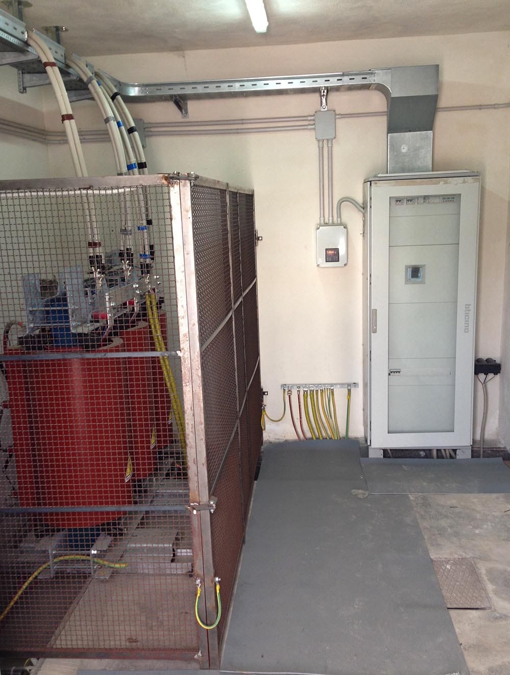
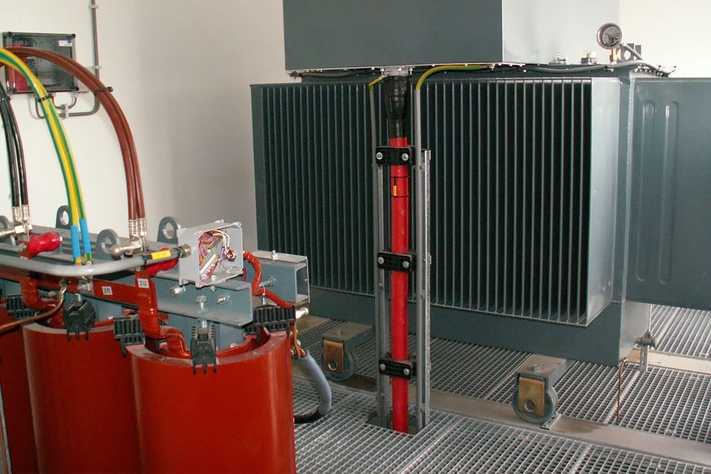
Figure 11 – 11/0.4 kV dry-type substation transformer
Using the fans for regular day-to-day use is not recommended. Whatever type is supplied, and wherever located, heat loss from a transformer makes ventilation important. Even at an efficiency of 99%, there can still be many kilowatts of heat to be dissipated in a confined space!
It is usual for a transformer to be delivered ready for service, and it is recommended that the installation engineer does not remove the lid unless there is evidence of some abnormality.
It is seldom that a small or medium-sized transformer is shipped without oil; but if this should happen, or if the transformer has been in the store, it may be necessary to dry out the windings before commissioning the unit. If carried out at the manufacturer’s works, this would be done in a drying chamber, but on-site it should be done by circulating currents in the transformer windings.
It is then preferable that the oil be circulated through a filter plant at the same time. During the drying-out test, regular readings of the insulation resistance of the winding should be taken and checks made on the electric strength of the oil. The drying-out process is likely to take several days.
Where large transformers are concerned (say above 10 MVA), it would be foolish to proceed with any pre-commissioning or commissioning tests without enlisting the aid of the manufacturers.
Suggested Course – Transformer Theory, Design, Construction, Protection & Maintenance
Electrical Transformer Theory, Design, Construction, Protection and Maintenance
Go back to the Contents Table ↑
References:
- Electrical Engineer’s Reference Book by M. A. Laughton CEng., D. J. Warne CEng.
- Design and installation of low voltage busbar trunking systems (verified to BS EN 61439-6) by BEAMA
Related electrical guides & articles


Edvard Csanyi
Hi, I'm an electrical engineer, programmer and founder of EEP - Electrical Engineering Portal. I worked twelve years at Schneider Electric in the position of technical support for low- and medium-voltage projects and the design of busbar trunking systems.I'm highly specialized in the design of LV/MV switchgear and low-voltage, high-power busbar trunking (<6300A) in substations, commercial buildings and industry facilities. I'm also a professional in AutoCAD programming.
Profile: Edvard Csanyi

Thanks, that was helpful
It’s very impressive and knowledgeable