
HV project design aspects
This technical article covers numerous substation project design elements, lists the steps of the construction process, and examines the environmental impacts and impact mitigation strategies for power transmission and distribution substation projects.
 The life of a power substation project: Design, construction, erection and commissioning
Most projects suffer due to lack of capability of the project proponent and an inept mindset among its engineers and designers that extensive inclusion of environmental mitigation measures in the project design leads to very high construction and O&M costs in the long-run.
At the planning stage itself, land availability is one of the main factors that govern the establishment of a substation project. This involves a contiguous piece of land that can infringe upon scarce populated/forest/cultivated land.
During project construction, deviations to broadly accepted construction practices are quite normal by EPC contractor due to casual approach toward incorporation of environment, health and safety measures in project implementation.
- Top Design Criteria
- Construction Practice, Their Environmental Impacts, Mitigation and Work Process
- Distribution Transformers (below 33 kV)
1. Top Design Criteria
For selection of appropriate site for substation, the following design criteria are usually taken into consideration by project proponents:
Consideration #1 – Site selection should consider seismicity and geography of the local area; the area should not be prone to landslide or located in unstable marshy or flood prone areas.
Consideration #2 – Construction activities do not adversely affect the population living near the proposed substations and does not create any threat to the survival of any community with special reference to tribal community etc.
Consideration #3 – The location of substation does not affect any monument of cultural or historical importance.
Consideration #4 – Transformers and other equipment specifications compliant with government rules/regulations & International Electro-technical Commission (IEC) standards should be followed.
Consideration #5 – Construction techniques and machinery selection to be made with a view to minimize ground disturbance.
Consideration #6 – While planning for substations, drainage plan should be prepared to avoid seepage/leakages and pollution of water sources and natural springs etc.
Consideration #7 – Substation location/design to ensure that noise will not be a nuisance to neighboring properties.
Consideration #8 – Though the standard limits for electromagnetic interference are not prescribed, substation design will incorporate best suited technology and technique to minimize the electromagnetic interference within floor area.
Consideration #9 – Utility should adopt good practices and should always strive for a high standard of housekeeping for its substations and ancillary facilities.
Consideration #10 – Utility should incorporate the best technical practices to deal with environmental issues in its working.
Consideration #11 – Design of substations to include modern fire control systems/firewalls. Oil storage systems, provision of fire-fighting equipment would be located close to transformers, switchgear, etc.
Consideration #12 – For distribution substations, the above items remain the same however, the intensity of impacts get limited due to small size and lower voltages.
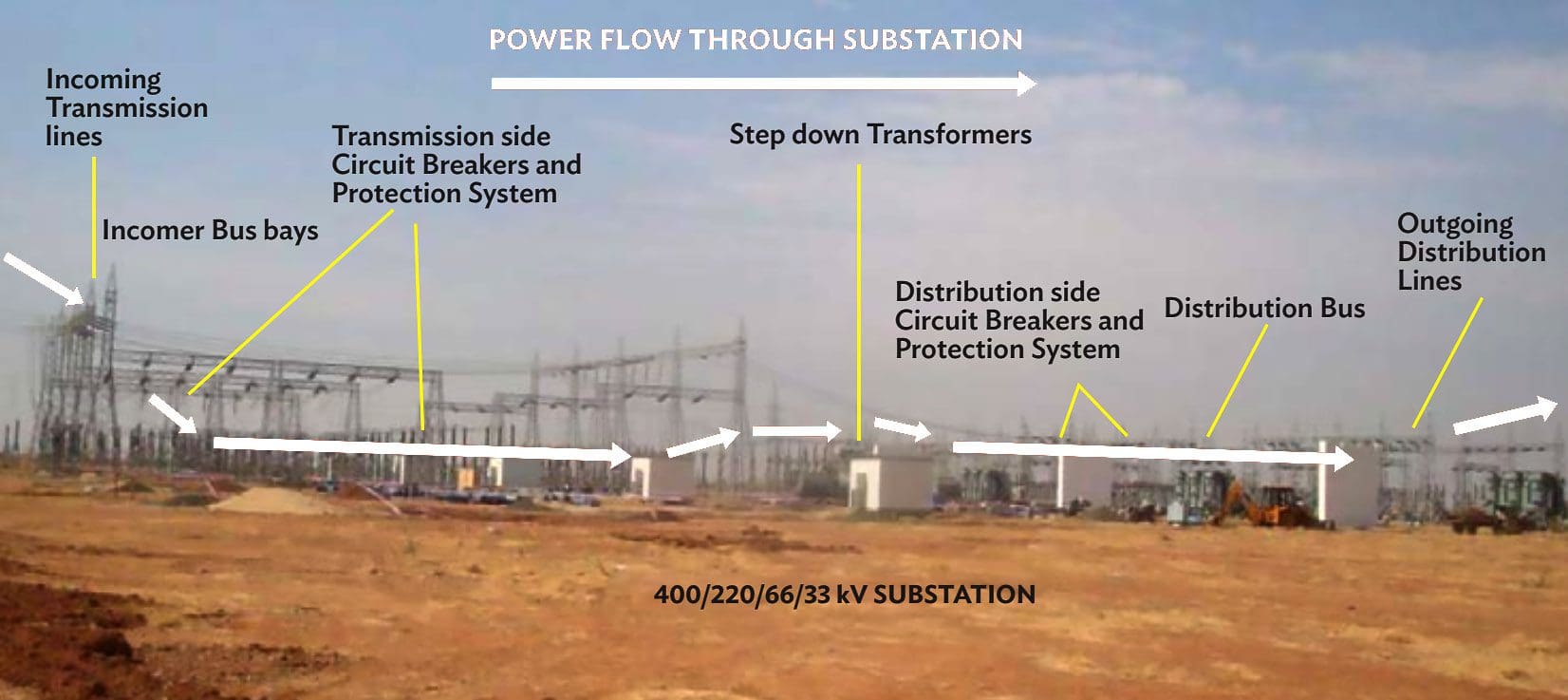
Figure 1 provides a schematic for the power flow from the incoming sub-transmission lines to outgoing distribution lines.
Figure 1 – Schematic Diagram of the Transmission/Distribution System Inside Substation
Go back to the Contents Table ↑
2. Construction Practice, their Environmental Impacts, Mitigation and Work Process
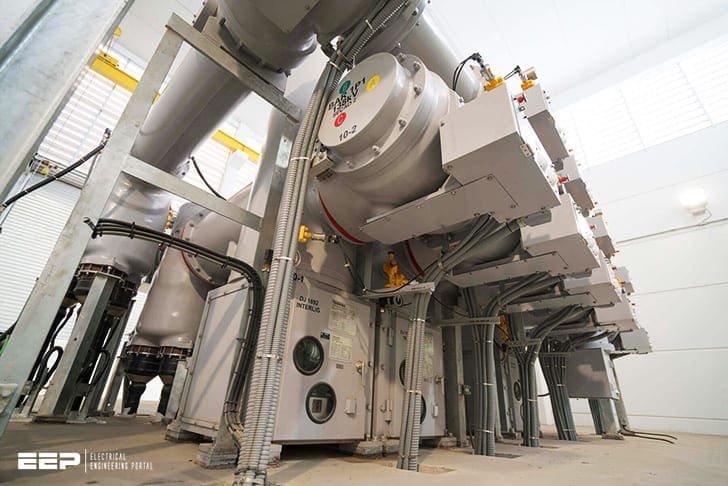
There are two types of electrical substation design that are used depending on the availability of land and its location – Air Insulated Switchgear (AIS) substation design where all equipment is erected outdoors where the land is available; while the Gas Insulated Switchgear (GIS) substation where all equipment besides transformer are erected both indoors and outdoors as shown in Figure 2, 3 and 4 below.
The GIS technology is used where the land is scarce such as highly populated urban areas, high hilly terrains or security reasons.
Figure 2 – GIS based substation equipment in 33/11 kV indoor substation
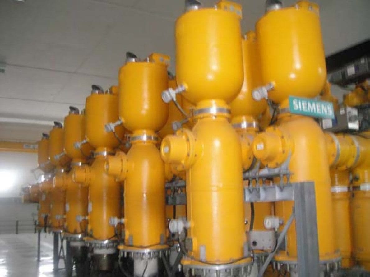
Figure 3 – GIS substation control room layout substation
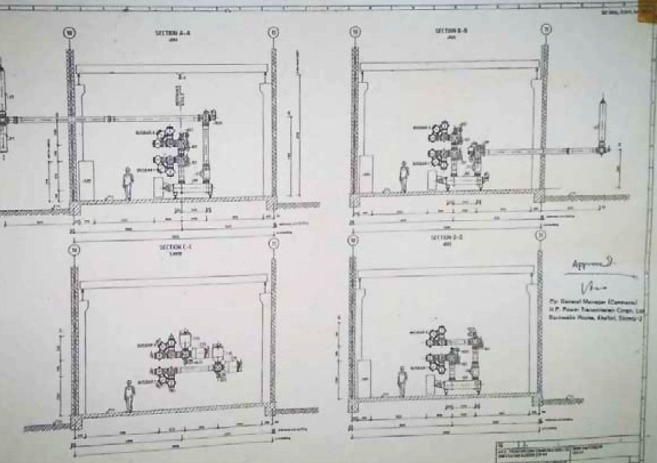
Figure 4 – AIS based substation switchyard equipment station

The AIS substation requires all its components to be situated in the switchyard and air serves as the insulating dielectric medium between different switchgear. Whereas the GIS substations are normally very compact and all equipment are enclosed in Sulphur Hexafluoride (SF6) envelope, a non-toxic greenhouse gas (GHG) used as a dielectric in circuit breakers, switchgear, and other electrical equipment.
GIS station uses very small size of land and building unlike the AIS. The equipment is designed to ensure prevention of even 0.5% leakage of the gas into the environment.
The Flow Chart in Figure 5 displays activities as they progress while constructing a transmission substation. On the left are the “Steps” involved in the process of project implementation such as “Pre Construction, Facilities Setup, Construction, Erection, and Commissioning”.
For example, The construction related environmental impacts usually occur during implementation of “Tasks” 5-17. These “Tasks” are usually performed by the Engineering Procurement and Construction contractor.
This articles provides information about each of the step involved in transmission line design, construction, testing and commissioning, the environment impacts and the proposed mitigation, and work process involved.
Each stage is represented as follows:
- Tasks: lists work undertaken to accomplish the “Steps” shown in Figure 6. This followed by explanation of the task conducted.
- Activity causing Impact and Location: lists the activity undertaken to accomplish each “Task” that impacts the environment and also gives the location of the environmental impact in brackets.
- Impact of activity and its type: describes the impact on environment of each activity and lists it type – temporary, permanent, planning etc. in brackets.
- Mitigation Measure for the Impact: lists environmental mitigation measures taken to mitigate the impact.
- Work process: provides a write up on the work done by EPC contractor for each “Task” and the human aspect involved during task completion.
- Each stage contains pictures from actual working sites that are mapped to each relevant “Activity”.
Figure 5 – Process Flow Chart for Construction of Transmission Substations
Go back to the Contents Table ↑
2.1 Preconstruction
2.1.1 Survey, Alternate Analysis
Reconnaissance Survey: Information on field data required for substation design, distance from community resources – worship place, village common grounds, community center’s schools, hospitals etc. Location of substation as compared to the direction of incomers and outgoing lines is an important factor in determining the site.
Alternative analysis survey: All alternative locations for the substations are proposed and collection of features observed and facilities marked on topographical map (1:50,000). See Figure 6. GPS coordinates are noted for each location finalized for surveys (See Figure 7).
Activity causing Impact and Location: Enumeration of trees for cutting, identification of- locations for digging of soil for foundations for equipment, buildings etc., stacking area for construction material etc. (Location: Substation land)
Impact of activity and its type: Potential impact on physical resources – Topography, possible loss of biodiversity in the area, interference with common property resources, public utilities such as roads, water, sewage facilities etc. (Type: Planning stage)
Impact Mitigation: Avoid biodiversity areas such as location near water body etc. Consider better choice of location to avoid issues regarding common resources with community and public utilities.
Work process: This activity takes the first initial 3-4 months to ascertain the alternative location, the alignment of power lines. Local public resistance to give free tower land may cause delays in preparing alternate analysis case.
Figure 6 – Alternative locations for substations
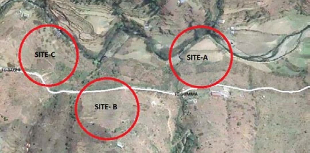
Figure 7 – Marking GPS locations for the future substation

Go back to the Contents Table ↑
2.1.2 Development of Environmental Baseline
Air, water, noise, soil investigation is the important aspect of the substation land in any area, such as hilly, plain level area, or sandy areas. General characteristics of the soil formation to be included in the plan, giving details of weather, clay, gravel, rock etc. that exist in the area as this information has a direct influence on the type of foundation types.
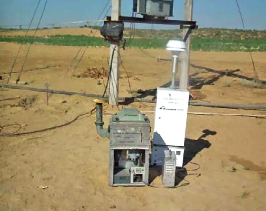
See Figure 8 for noise sampling and Figure 9 for air and dust sampling.
Activity causing Impact and Location: Collection of soil samples by using digging machines as well as collection of water from wells/water sources. (Location: Substation Land)
Impact of activity and its type: Minor impact of collection of soil samples using digging machines on topography or pollution of water source during sample collection. Marshy areas, low-lying areas, riverbeds, earth slip zones that would involve risk to stability of the foundations. (Type: Temporary)
Impact Mitigation: Development of baseline with no project situation a must for monitoring impact of project construction activities. Marshy areas are avoided. Care taken to ensure proper profiling of the ground rock formation and ground water.
Work process: Soil samples taken manually by digging machines and sink new tube well(s) in the planned premises for the substation.
Figure 8 – Noise Measurement

Figure 9 – Air dust samplers
Go back to the Contents Table ↑
2.1.3 Substation Layout
Electrical layout of the site is finalized. (See Figure 10) Facilities layout, selection of benches for substation (various levels in hilly areas), Cutting and filling for levelling land (See Figure 12). Development of drainage, road and other facilities (See Figure 11)
Activity causing Impact and Location: Development of benches by cutting and filling inside the substation sites to ensure proper placement of all equipment. – See Figure 13.
Benching allows voltage level separation by physically locating similar equipment in one bench. (See Figure 13)
(Location: Substation site)
Impact of activity and its type: Planned cutting and filling will lead to soil erosion, runoff of soil, potential water logging, suitable places to dispose excess soil, cutting of trees on the site. (Type: Planning)
Impact Mitigation: Water logged/steep sloped/degraded sites must be avoided while selecting the location of substation. The layout of the site must be such that cutting of trees, soil must be minimized. Extreme slopes need to stabilized for avoiding soil runoff (See Figure 14)
Work process: Preparation of site level contour mapping, coordinates, enumerating number of trees to be cut, plotting location of building, position of various equipment, control rooms, access roads etc. on to the profile sheets.
Figure 10 – Electrical drawing for substation
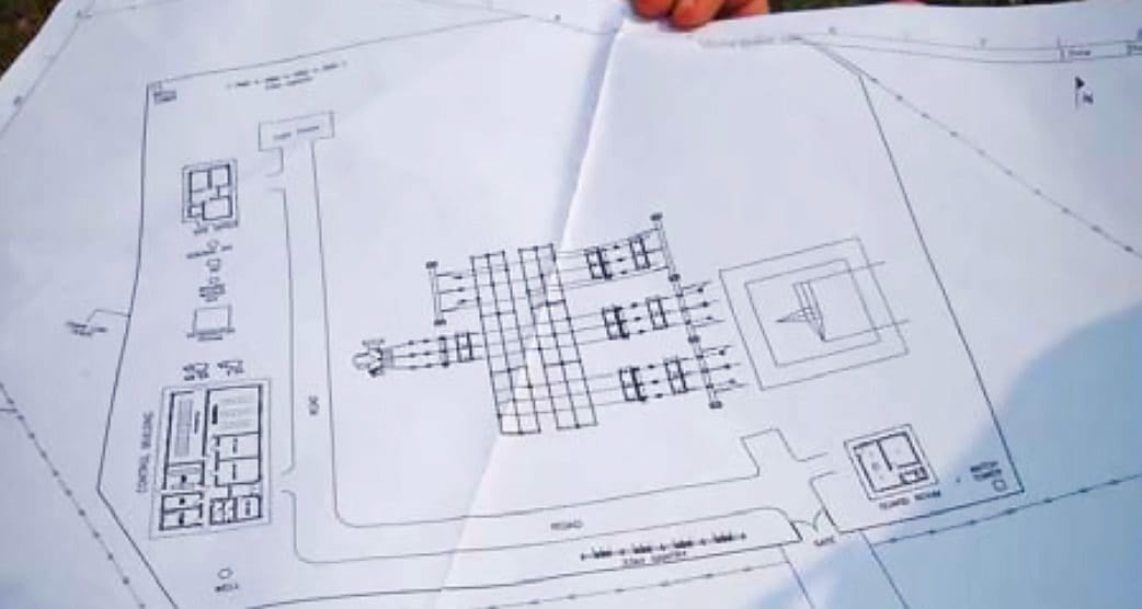
Figure 11 – Substation layout (blue gives drainage plan; rectangles give the benching placement locations of control room, transformers, other equipment, roads, etc.

Figure 12 – Cut and fill of soil for substation land. (blue is current hill profile. Three benches are designed for placement of equipment, transformer, road etc.)
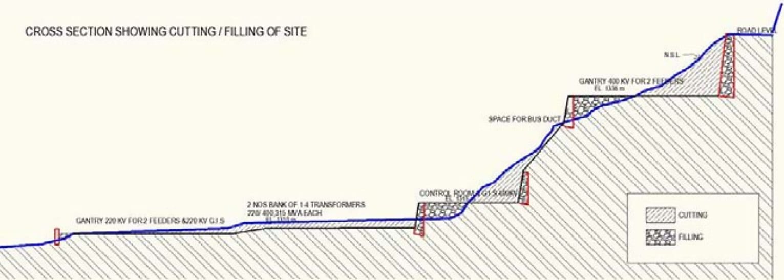
Figure 13 – Benching inside substation land
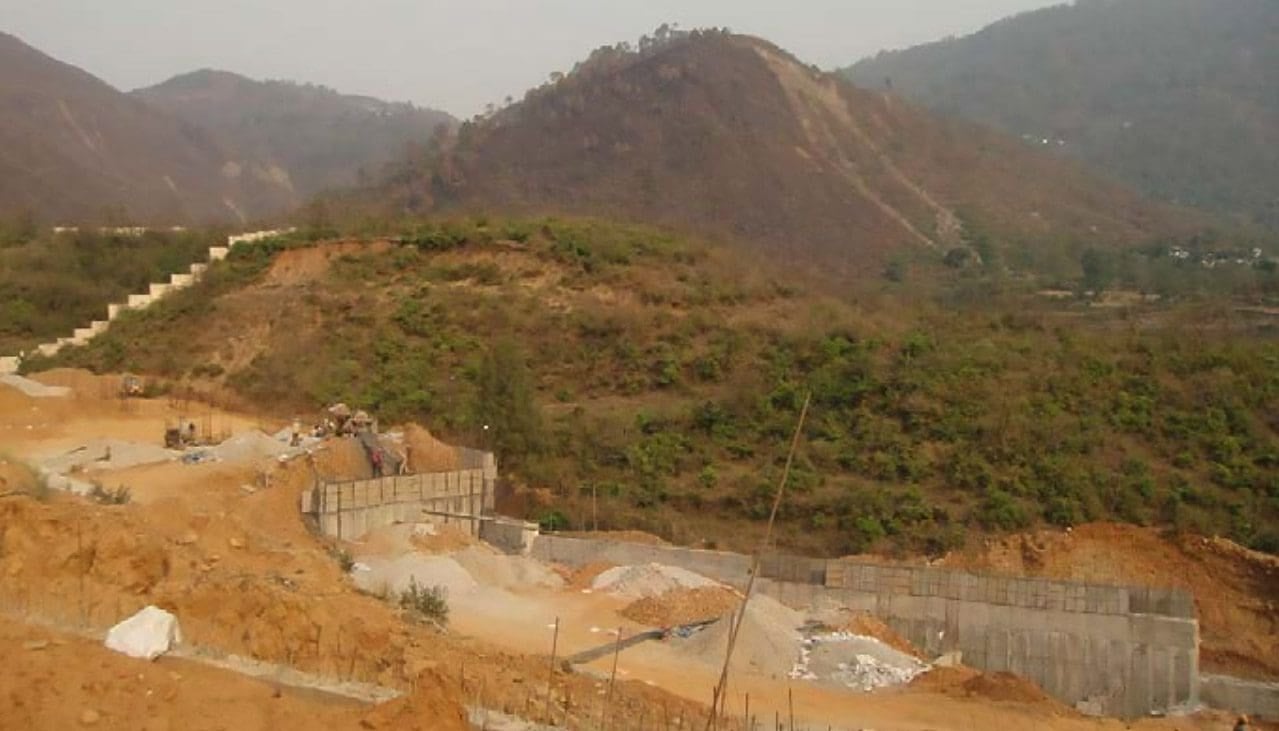
Figure 14 – Proposed sloping substation land

Go back to the Contents Table ↑
2.1.4 Sizing of Equipment, Type and Capacity
Sizing of all substation equipment: The numbers are required in substation according to no. of load centers to be connected and the
corresponding incoming power from power generation sources (either type of generation – renewable and non-renewable sources).
Substation has several equipment that are included in design. See Figures 15 to 18.
- Circuit Breakers (vacuum/oil) (CB),
- SF6 Circuit Breaker,
- Isolators with and without earth Switch,
- Current Transformers (CT),
- Capacitor Voltage Transformers (CVT)/Voltage Transformers (VT),
- Surge Arrestors,
- Bus Post Insulators and Bus bars,
- Potential Transformers (PT),
- Lightning Arrestors (LA),
- etc.
Activity causing Impact and Location: Type of equipment installations/foundations planned as per electrical layout plan (Location: Substation land)
Impact of activity and its type: Potential digging for foundations and surface runoff of soils and any leaching of oils to ground water. (Type: Planning)
Impact Mitigation: Plan for proper location analysis to ensure appropriate distances, installations of equipment, proper access roads etc.
Work process: The equipment will be outdoor for AIS substation and indoor for GIS substation. Such equipment are normally handled using mechanized boom cranes.
Figure 15 – Isolators for incoming (Incomer) lines
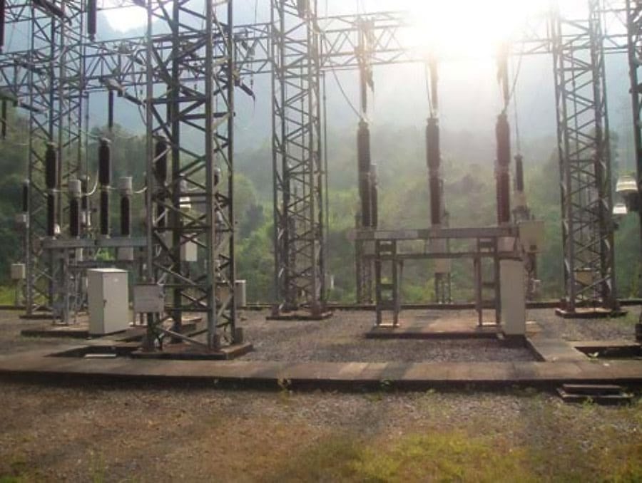
Figure 16 – Other equipment: AIS equipment
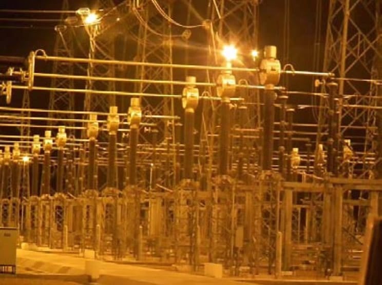
Figure 17 – Line isolators
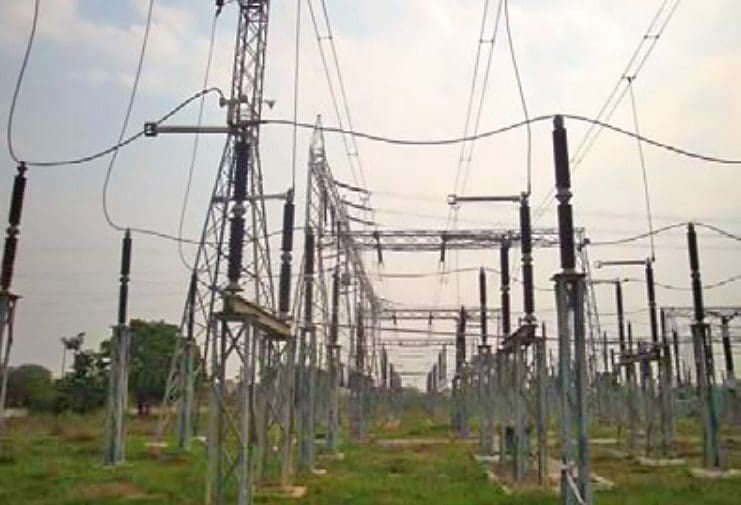
Figure 18 – GIS based substation equipment Indoor
Go back to the Contents Table ↑
2.2 Facilities Set Up
2.2.1 Temporary Worker Camps
The worker camps are temporary in nature and will be used until facilities are fully constructed. These camps are normally made at the substation site and the strength of man-power is between 10-20 workers for a maximum of 6-12 months until construction is complete.
Activity causing Impact and Location: Scatter of kitchen waste, toilet waste, wastewater, scrap, unusable/nonrecyclable waste in camps. Poaching of animal life, fishing, harvesting of wood by workers. (Location: Worker Camp)
Impact of activity and its type: Oils, untreated wastewater, sewage etc. flowing into water body, river, drainage areas from the camps causing impact to surface water, ground water, any aquatic life downstream in the area. The downstream water in river can be polluted making it unfit for bathing or potable water.
The camps can also adversely impact on ecological resources through poaching of wildlife and using wood from trees as firewood in the area (Type: Temporary)
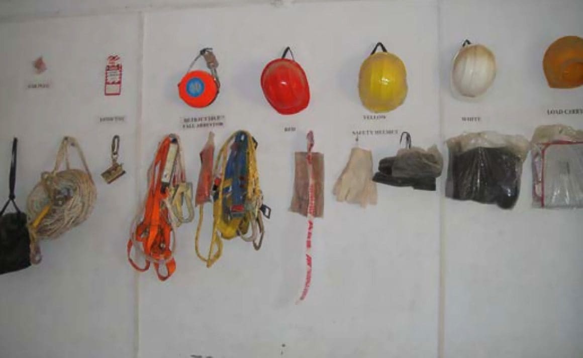
Impact Mitigation: Contract provisions must specify minimum setback requirements for construction camps from water bodies, reserved areas etc. Contractor to provide liquefied petroleum gas cylinders for cooking, safe drinking water, washing and toilet facilities and sanitary soak-pits (See Figure 19), medical facilities (See Figure 20) at the construction site for the workers.
Work process: Contractor establishes a camp that has proper facilities – camp, drinking water, sanitation, electricity, toilets, medical facility before the start of construction at substation.
Figure 19 – Proper toilet facilities at substation construction site
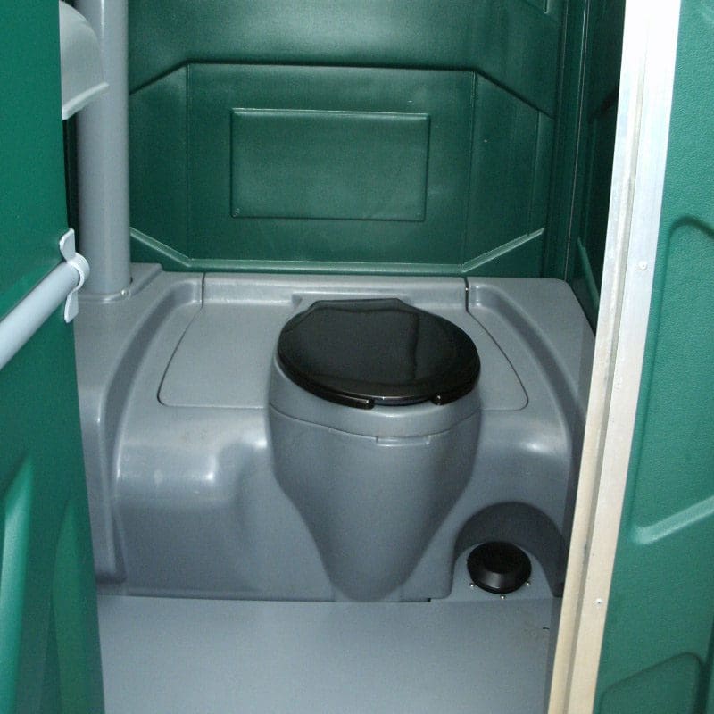
Figure 20 – Medical Facility and display of Personal Protective Equipment (PPE)
Go back to the Contents Table ↑
2.2.2 Unloading of Material at Site, Storage and Workshop
Substation sites are accessible by roads to mechanized equipment for unloading, while some are manually unloaded using chain and pulleys blocks.
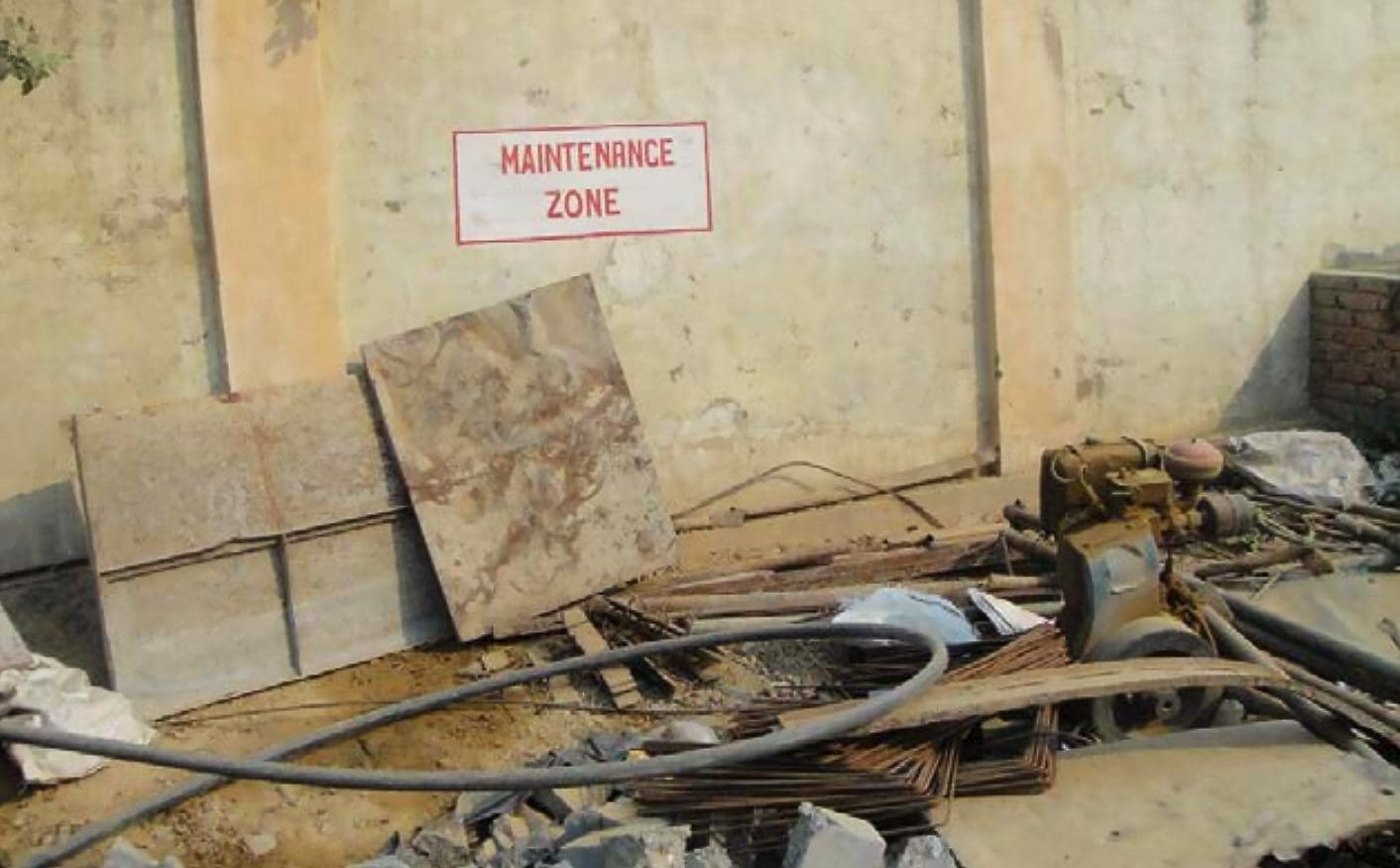
Activity causing Impact and Location: Levelling of storage place and cutting of trees to establish workshop, stores (See Figures 21 and 22) and designated maintenance areas (See Figure 23).
Stores have storage of oils, and chemicals; the workshop for steel cutting welding etc. Toilets for workers will be constructed. Transportation of equipment to sites using heavy cranes to unload equipment. (Location: Stores, machine shops)
Impact of activity and its type: Impact on terrestrial ecology – tree cutting, disposal of scrap, unusable/nonrecyclable waste. Impact on air quality/noise levels due vehicle emissions and water quality – toilet waste, oils, sewage, slurry from workshops flow into the ground or into surface water polluting the land and water body affecting aquatic life. (Type: Temporary)
Impact Mitigation: Selection of approved locations for material storage yards and workshops away from the environmental sensitive areas.
Work process: Creating storage facility, transportation, unloading, storage and usage normally would take between 6-8 months for any substation project.
Figure 21 – Cable storage for underground wiring
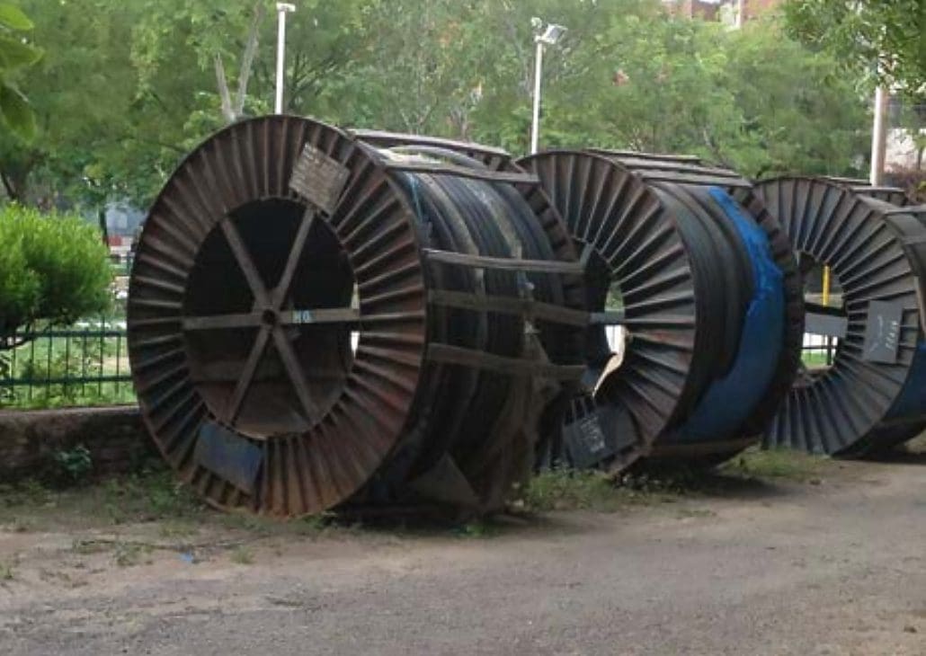
Figure 22 – Storage of Equipment
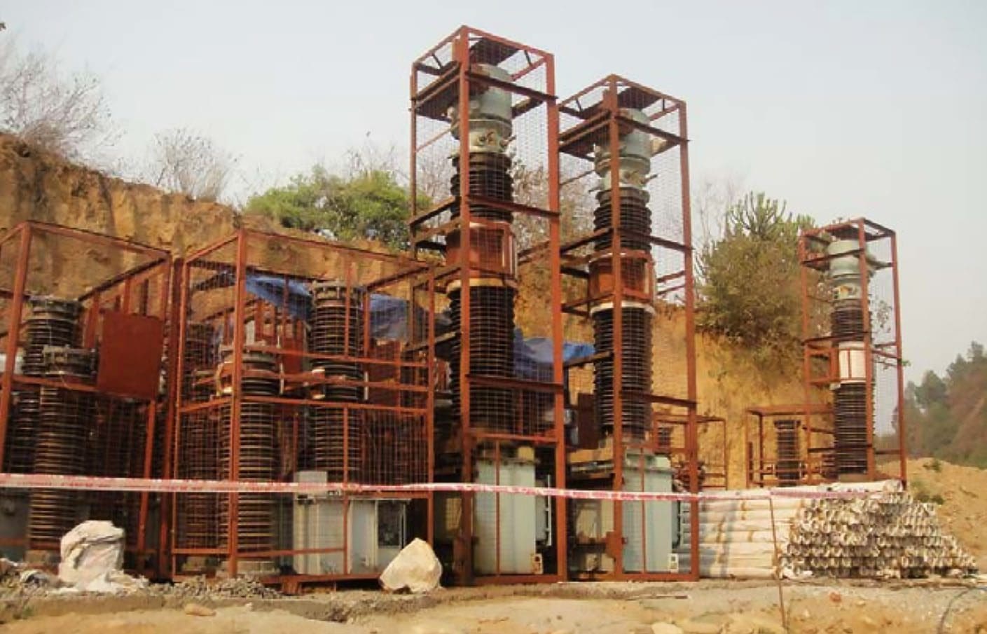
Figure 23 – Designated Maintenance Area
Go back to the Contents Table ↑
2.3 Construction
2.3.1 Digging Pits, Bending Steel Wires, Reinforced Cement Concrete (RCC)
Bending steel rods, tying with steel wires and mixing concrete for the foundation is done manually. This is followed by pouring concrete prepared using a manual mixing machine. This steel-concrete structure is known as Reinforced Cement Concrete (RCC). The concrete is casted manually into the foundations and footing prepared manually using ply-boards and/or wood casts made as per design.
See Figure 24.
Activity causing Impact and Location: Surface run-off of prestacked soil, oil leakages from engine and vehicles. Steep contour, improper soil type encountered. (Location: Substation land)
Impact of activity and its type: Ground and surface water quality, aquatic ecology may be affected due to surface soil run-off, dripping of oils from engines of digging machines. Steep contour, improper soil type encountered making the foundations very huge and contour specific requiring revetmen. See Figure 25. (Type: Temporary)
Impact Mitigation: Restore the loose soil from foundations through ramming. Dispose of excess soil spread out in areas that do not interfere with local drainage pattern.
Work process: Foundation construction takes between 6-12 months depending upon the size of substation. Any major RCC foundation/structure
would need about 1-2 weeks for construction.
Figure 24 – Steel and concrete foundations
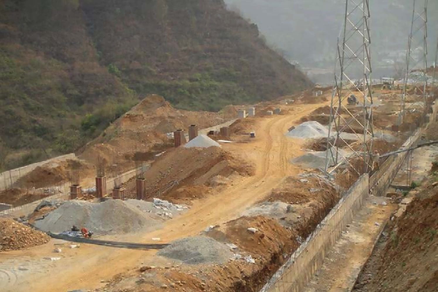
Figure 25 – Concrete walls to stabilize the land area which is in various levels

Go back to the Contents Table ↑
2.3.2 Constructing Foundations, Control Room Building, Pathways, Cable Trays
The foundations casted manually using prefabricated ply boards and/or wood casts made as per design and concrete is poured manually. Control rooms (CR) include control wires, housing cable trays, bays for panels, battery room etc. Other structures include transformer foundation, cable trays, plinths for auxiliary transformer, etc. Erection of Earth-mat inside the entire substation boundary.
Activity causing Impact and Location: Digging and concrete casting of foundations for structures, transformers (See Figures 26 and 27), pillars/columns for buildings, trenches, cable trays (See Figure 28), road, drainage etc. (Location: Substation Control Room, and switch yard area)
Impact of activity and its type: Solid waste generation at the substation site will include metal scraps, wooden packing material etc.
Excess soil from foundations/ muck will be laid out in areas that may interfere with drainage of the area. (Type: Temporary)
Impact Mitigation: Concrete waste, wooden waste and metal scrap will be collected and disposed to offsite in compliance with applicable regulations and rules. Contractor to manage waste generated from the construction sites without contamination to natural environment and it will reduce risk to public who stay close to sites.
Ensure proper drainage system is constructed.
Work process: Civil Construction works normally take up to 3-12 months depending on size of the substation. The construction workers may live at the site or may be local residents of the area.
Figure 26 – Construction of Transformer bay

Figure 27 – Manual construction of room

Figure 28 – Cable Trays within substation

Go back to the Contents Table ↑
2.3.3 Switchyard Earthing, Civil Work For Equipment Foundations and Structures
Installation of switchyard lighting, communication and firefighting system. The foundations for structures (See Figure 29 and 30) and equipment are also casted manually using prefabricated ply boards and/or wood casts made as per design and concrete is poured manually. Earthing of each structure is done within the yard.
Activity causing Impact and Location: Digging and concrete casting of foundations for structures, earthing of equipment. (Location: Substation Control Room, and switchyard area)
Impact of activity and its type: Solid waste generation at the substation site will include metal scraps, wooden packing material etc. Wastewater may also be generated at site. Excess soil from digging of structure foundations if laid out in areas may interfere with drainage of the area. (Type: Temporary)
Impact Mitigation: Concrete waste, wooden waste and metal scrap will be collected and disposed to offsite in compliance with applicable regulations and rules.
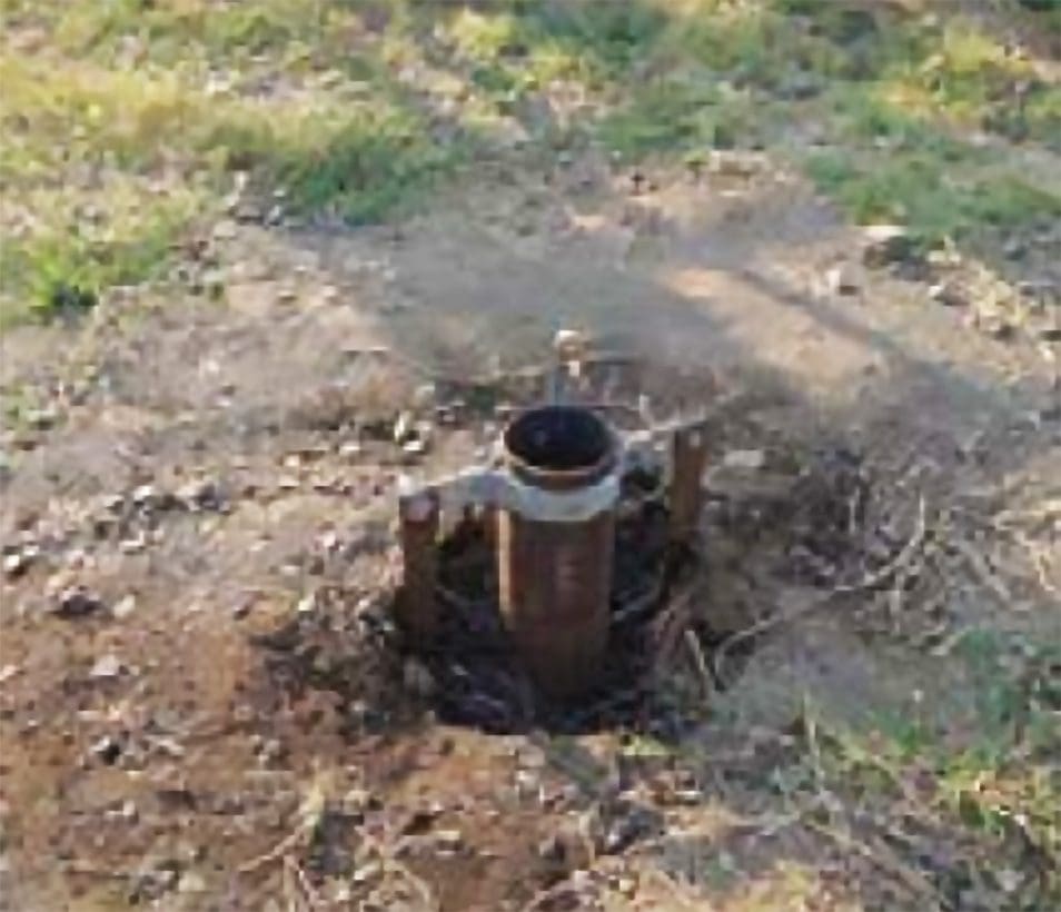
Work process: The foundations require digging and erection of foundations for structures in the outdoor switch yard. Pipe earthing (as shown in Figure 31) is usually used in all substations to ensure double earthing for each equipment and structures.
Figure 29 – Switchyard structures
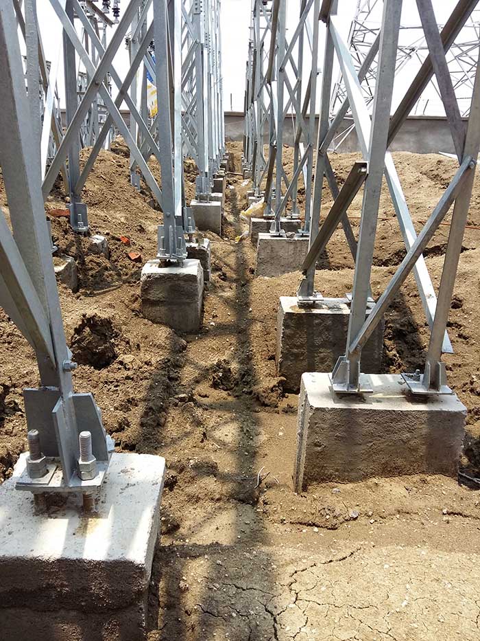
Figure 30 – Switchyard structures
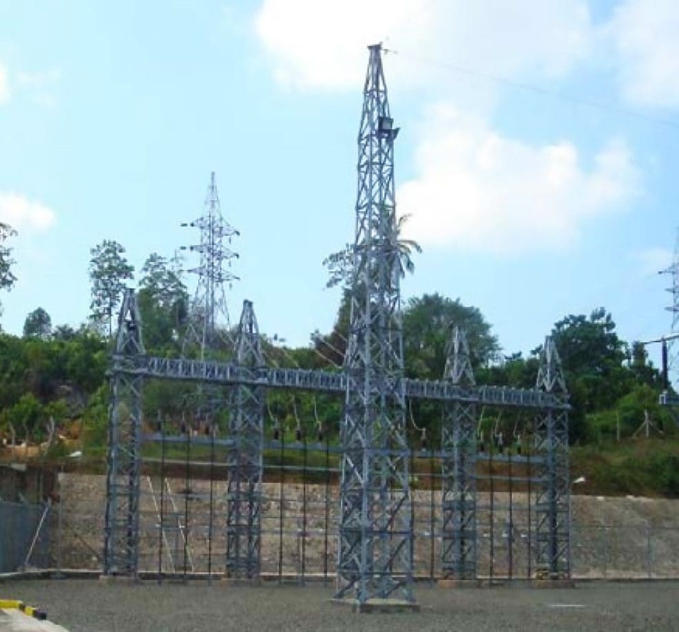
Figure 31 – Pipe earthing in switch yard
Go back to the Contents Table ↑
2.4 Erection
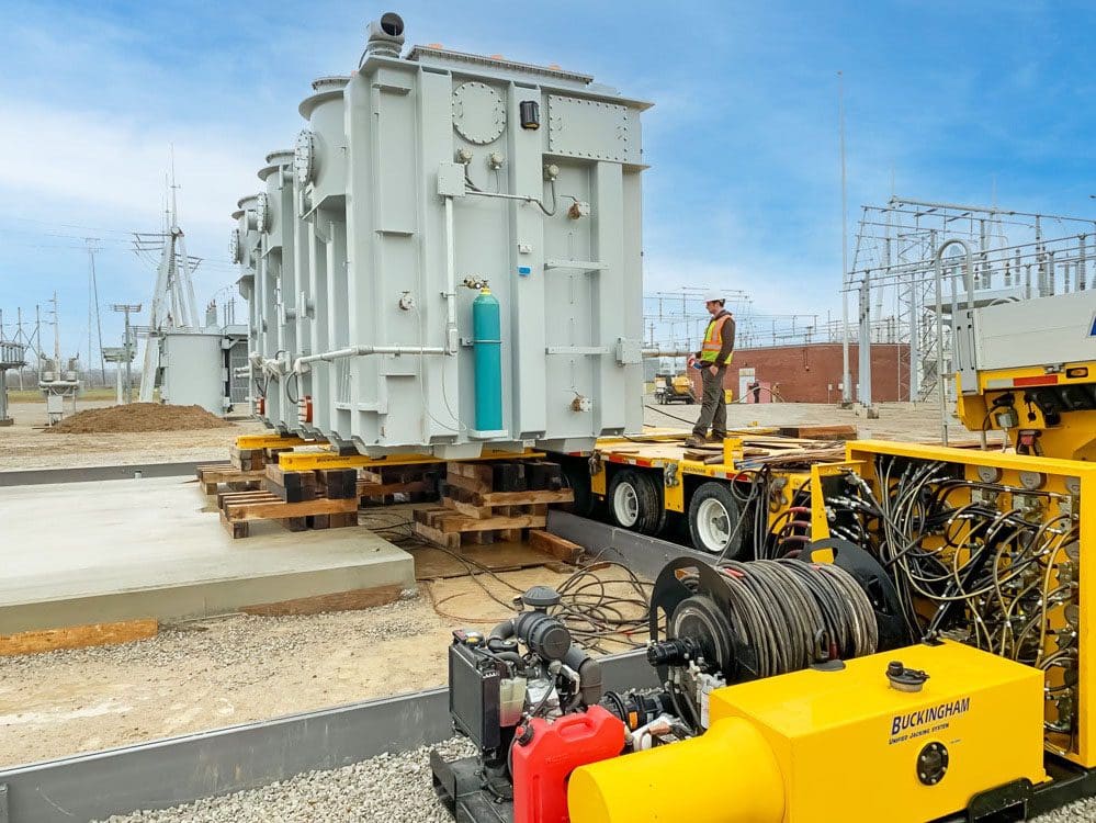
2.4.1 Unloading and Erecting Power Transformer
Power transformer is usually brought to the site using specialized flatbed trailer and high capacity truck to remote areas in the hilly terrains as well as the level areas.
Activity causing Impact and Location: Transportation of transformer to the site on flatbed trailer (See Figure 32) , unloading and erection of the power transformer on the Transformer bay (See Figure 26 above) (Location: Road access).
Impact of activity and its type: Improper road access and road bridges that can withstand the weight of the transformer to the site causing delay in transportation and unloading. (Type: Temporary)
Impact Mitigation: Ensure bridges are tested for weight capacity and road widened enough in hilly areas so that the transformer could reach the site.
Work process: Unloading of the transfer is usually done manually using sleeper and jacks because of unavailability of high capacity cranes to unload them. See Figure 33.
In a freak case, the transformer may have to be taken off the truck trailer mid-way of transportation and stored temporarily until road/bridge which is broken/ unsafe due to avalanches, landslides is repaired or the weather condition such as heavy monsoon, snow, blizzards etc. clears out.
Figure 32 – Transportation of power transformer
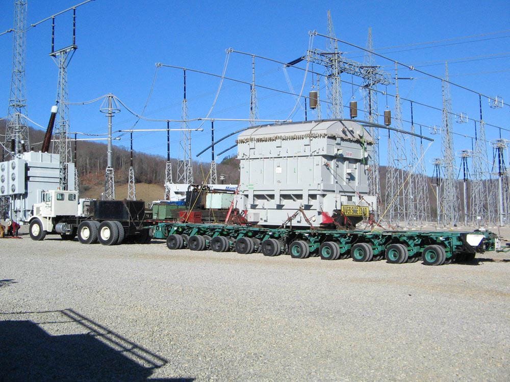
Figure 33 – Unloading of transformer using Jack & Slide System
Go back to the Contents Table ↑
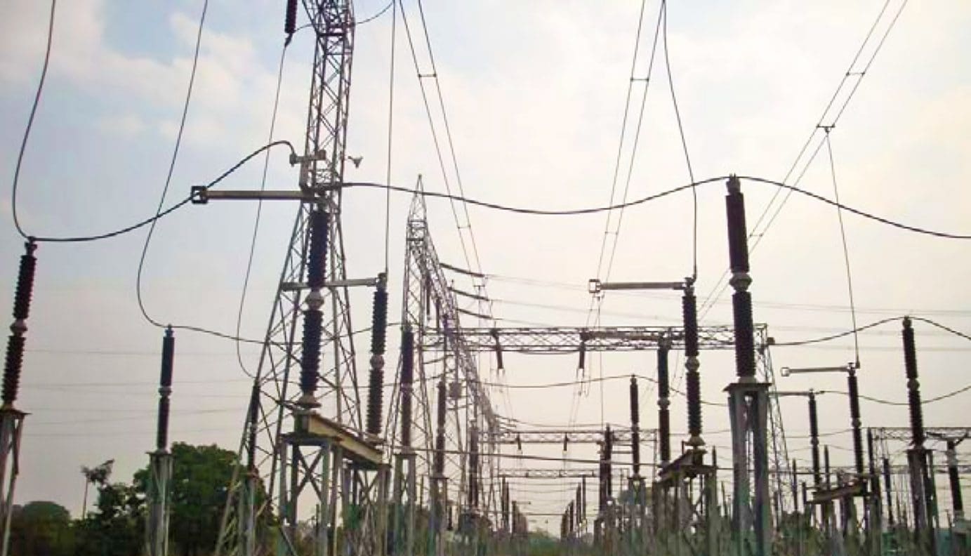
2.4.2 Erection of Substation Bus Bars, Bus Coupler all Bus Items
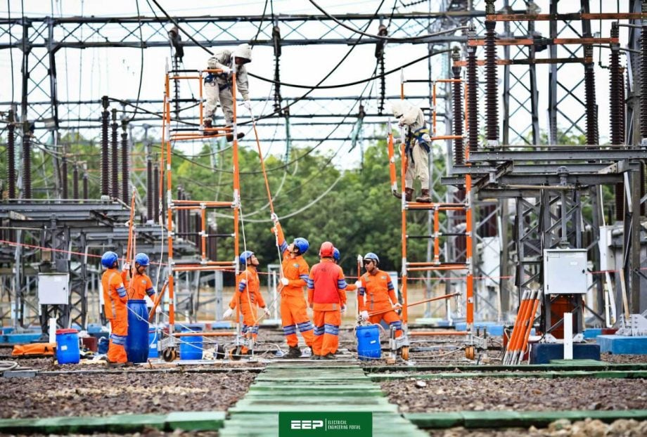
The substation bus bar structure along with all CTs, PTs, Isolators, surge arresters (See Figure 34) are erected manually/using chain pulleys. As per transmission towers, manual pulleys are used to lift the towers parts and fittings to the lattice type horizontal/vertical beam structure (See Figure 35) as well as to the bus bar connectivity (See Figure 36).
Activity causing Impact and Location: Personal Protective Equipment (PPE’s) not used by workers. (Location: Substation site)
Impact of activity and its type: Unsafe erection of tower can result in injuries to the workers. Untrained workers can lead to more accidents and fatalities. (Type: Temporary)
Impact Mitigation: Construction manpower to use PPE at site at all times.
Work process: A typical horizontal/vertical beam structure erection takes at least a team of 5-8 workers for a month.
Figure 34 – Erection of substation equipment
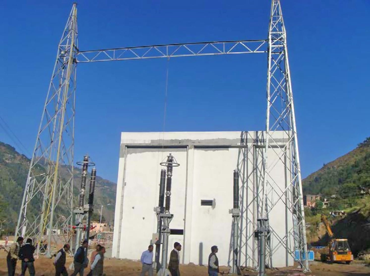
Figure 35 – Lattice box type beam structure
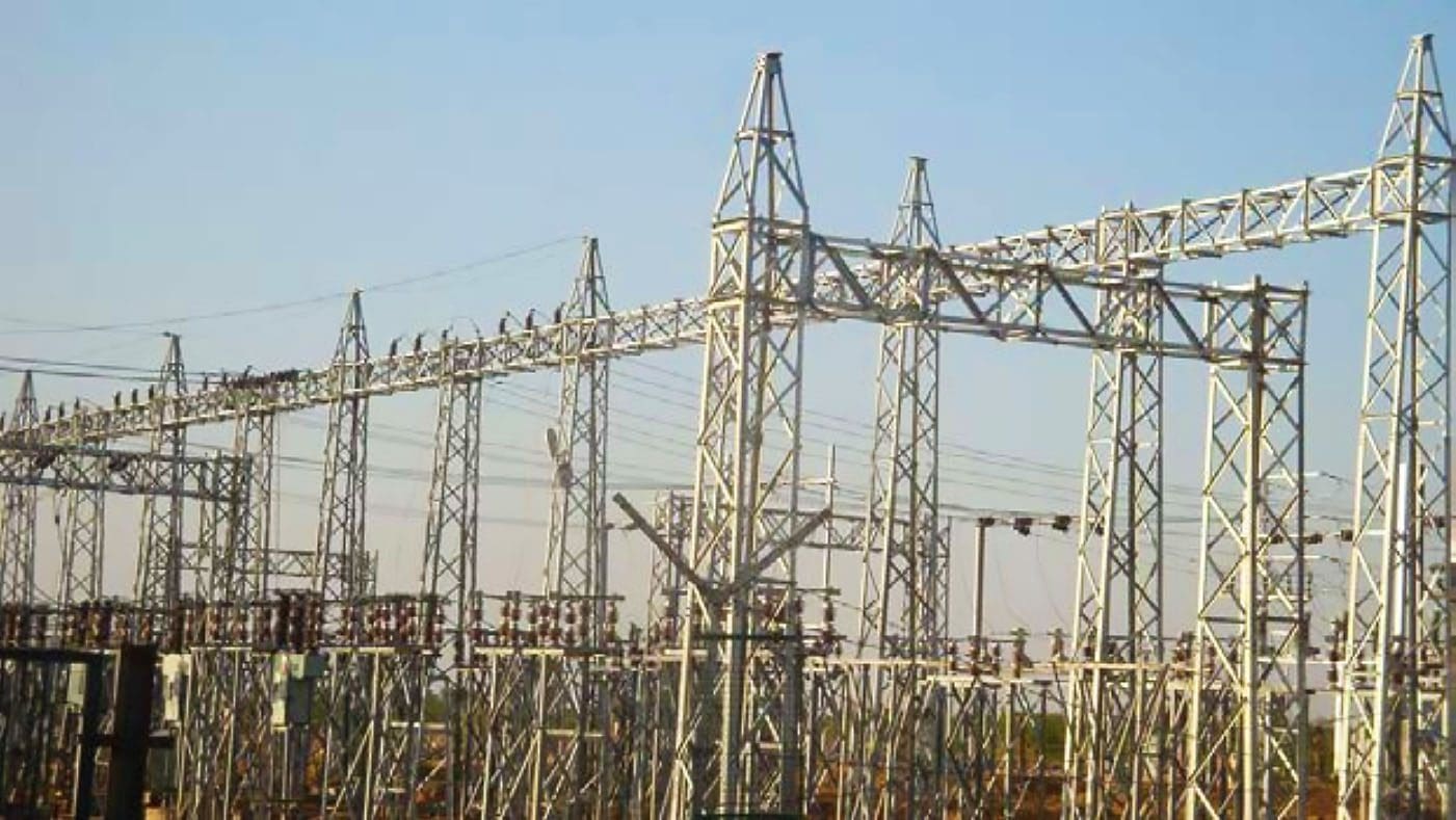
Figure 36 – Bus Bar connections through line isolators
Go back to the Contents Table ↑
2.4.3 Erecting Transformer and Line Bays, Incoming and Outgoing Lines, Terminal Gantries
At any substation a minimum of one incoming transmission line (See Figure 37) and 2-3 outgoing transmission/distribution lines are erected (See Figure 38).
Activity causing Impact and Location: Location of terminating towers outside the substation (e.g. See single tower outside substation land in Figure 37) and similarly for outgoing lines (See lattice structures in Figure 38) and terminal gantry (See in Figure 39). Erection of adjoin Bus bars and transformer bays. See in Figure 40. (Location: Tower bases)
Impact of activity and its type: There will be numerous terminating gantries for incoming and outgoing lines near the switchyard boundary causing problems to local community and making their agricultural fields useless. In case of electric short/blowout, the adjoining bay transformer and equipment may get affected. (Type: Permanent)
Impact Mitigation: Proper survey of incoming and outgoing lines to a substation to ensure the adjoining agricultural land required is minimized and the owner is compensated. Erection of firewall between two transformer bays to ensure protection from fire accidents.
Work process: The incoming and outgoing gantry cannot be deviated as it is normally aligned with the incomer and outgoing bays of the substation; hence the project proponent must ensure proper alignment as the time of design to avoid buildings etc. The area under the tower is not usually paid as compensation to the landowner.
If there are two-three lines passing in his yard, his land becomes basically useless for mechanized agriculture.
Figure 37 – Transformer bay and bus bar
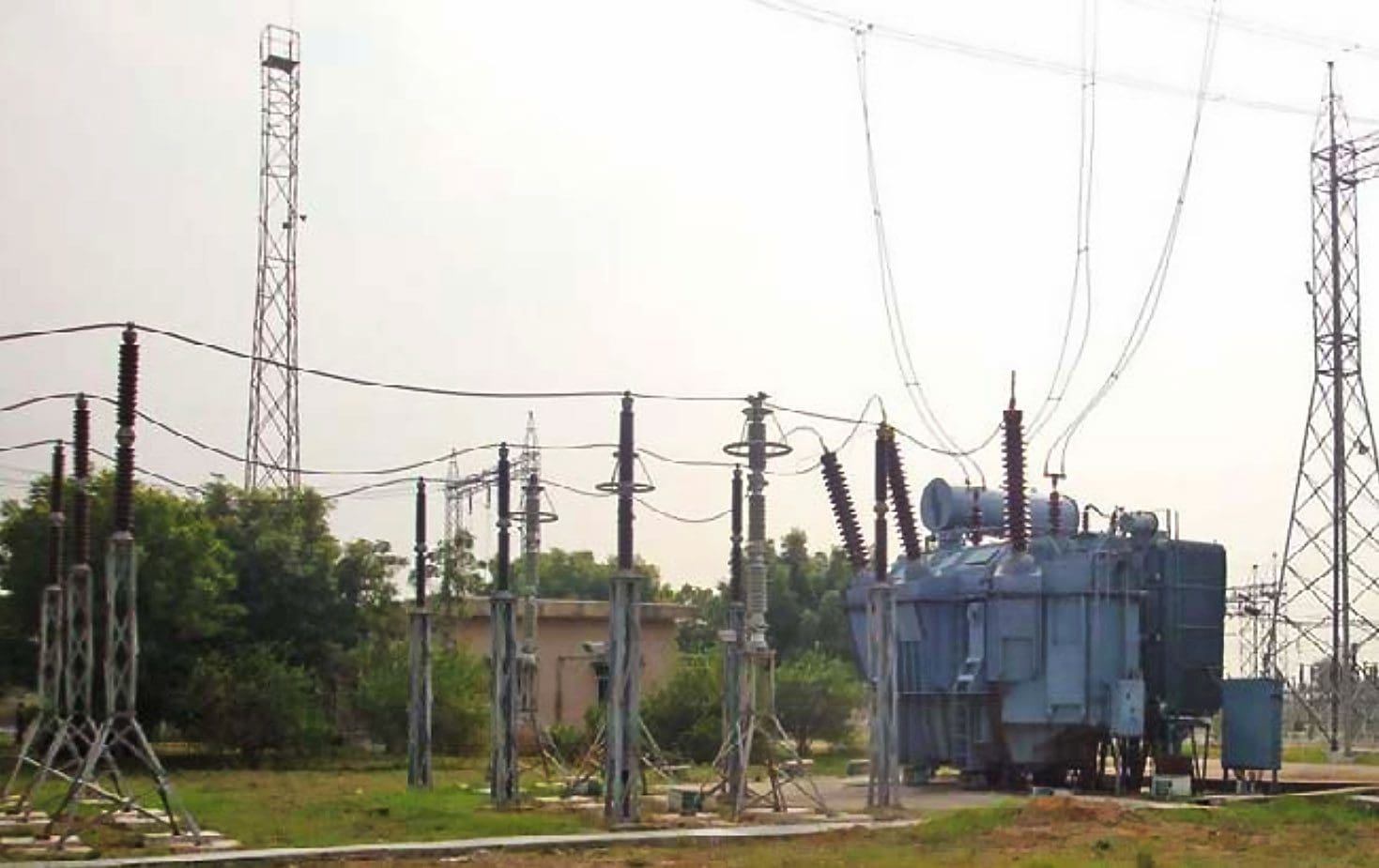
Figure 38 – Outgoing feeder bays and lines
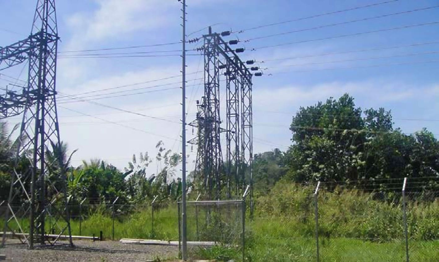
Figure 39 – Substation terminal gantry

Figure 40 – Bus bar, transformer bays separated by firewall
Go back to the Contents Table ↑
2.4.4 Transformer Oil Filling, Storage of Battery Water, Battery Bank etc.
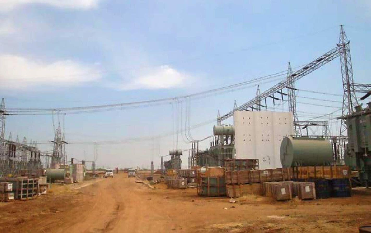
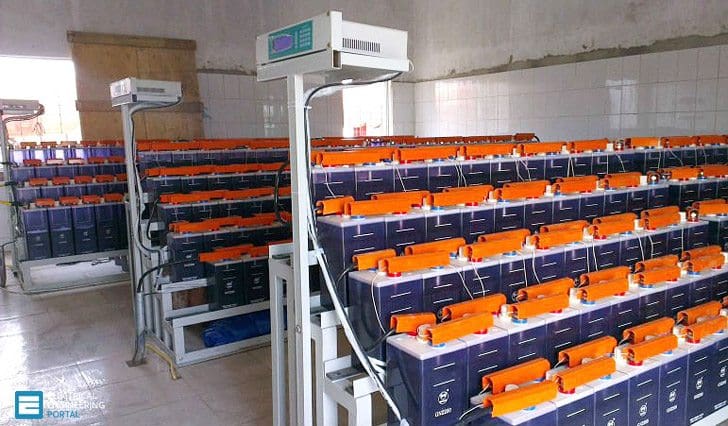
Transformer oil and battery banks are essential part of storage facilities at substation control room and storage yard.
Activity causing Impact and Location: Storage of equipment, transformers, oils (See Figure 41 and 42), fuels, battery water, other chemicals (See Figure 43) battery bank (see Figure 44) and at the project site for erection and filling. (Location: Transformer bay and battery room)
Impact of activity and its type: Contamination of land and or nearby water bodies by transformer oil, fuels, chemicals, battery water etc. can occur during erection and operation due to leakage or accident. (Type: Temporary)
Impact Mitigation: Proper drainage facilities will be constructed to avoid overflow or contamination of water bodies, streams, river etc. especially during the rainy season. Storage of bulk fuel should be on covered concrete pads away from the public and worker camp. Fuel storage areas and tanks must be clearly marked, protected and lighted.
Maintain account of the usage of oil through oil monitoring mechanism, and have mitigation plan for any oil spillage.
Work process: Substation transformers are normally located within secure and impervious areas with a storage capacity of 110% spare oil.
Figure 41 – Improper Transformer oil storage

Figure 42 – Transformer oil filling and circulation machine

Figure 43 – Storage of chemicals and battery water

Figure 44 – Substation battery bank (on photo: 110V substation NiCd battery system)
Go back to the Contents Table ↑
2.4.5 Control Room, Accessories and Switchyard
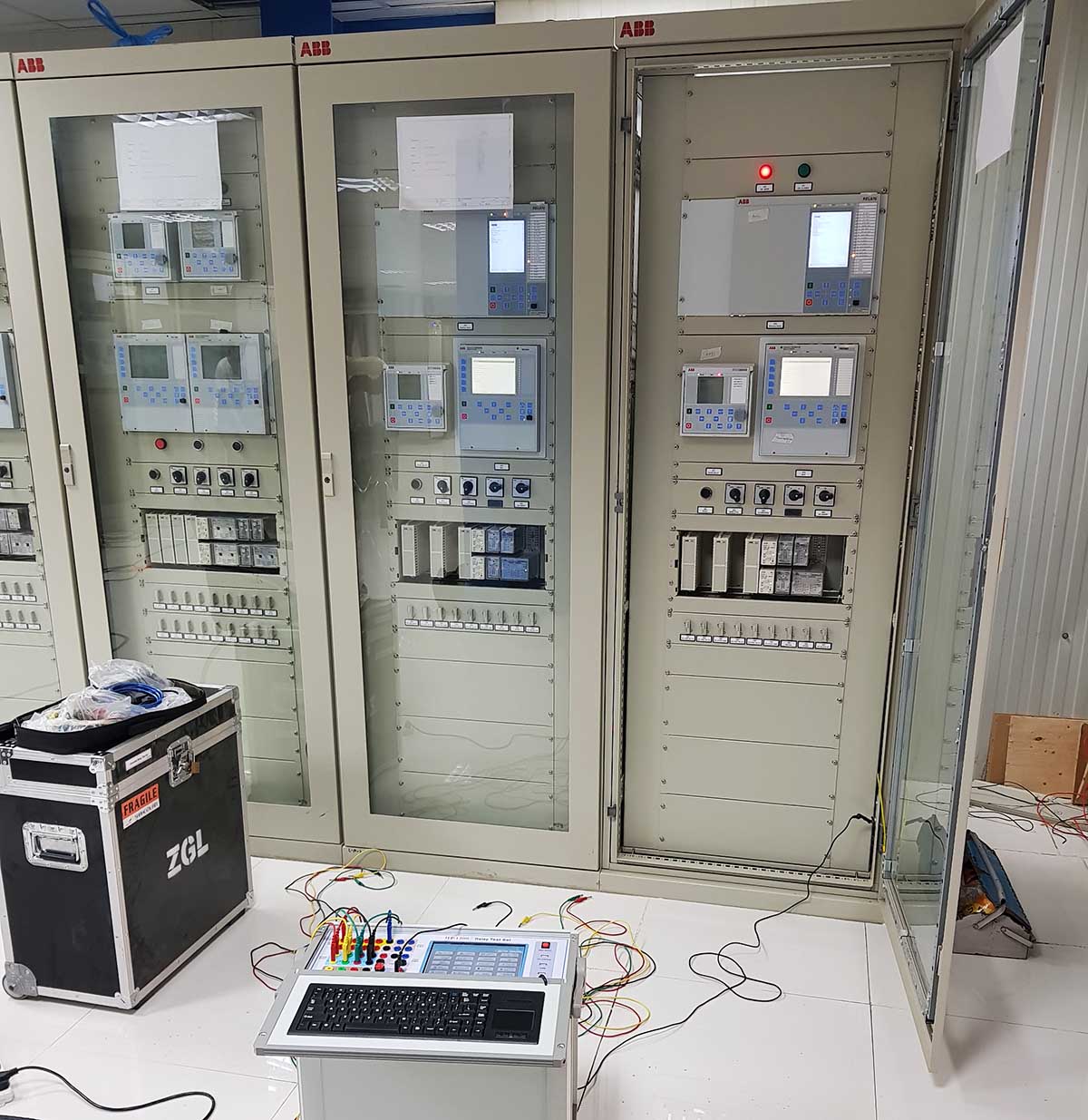
The control room buildings have both alternating (AC) and direct current (DC) distribution room facilities such as battery & charger room, Power line carrier communication (PLCC), substation automation (SA) system, Control Room (CR) Panels, Circuit Switchers, HV AC (heating, ventilation, and air conditioning) and normal & emergency AC & DC lighting, firefighting equipment etc.
Activity causing Impact and Location: Connectivity and internal wiring in Control room panels for bays (See Figure 45) Storage of SF6 gas cylinders. (Location: Substation switchyard)
Impact of activity and its type: Short circuits, fire due to improper connectivity, overload or accident. Inapt storage of SF6 gas cylinders, untracked leakage of SF6 from equipment. (Type: Temporary)
Impact Mitigation: Ensure correct connectivity of wiring, availability of firefighting equipment (See Figure 46) maintained in working order at construction site. Ensure fully trained personnel handle interconnections, wiring, chemicals, tracking of leakage of SF6 from circuit breakers etc.
Work process: Internal wiring is done by highly specialist technicians well versed in the manufacturer equipment installation. Depending on the
numbers, each module of the panel would take between 1-2 weeks to complete. See Figure 47.
Figure 45 – Control Room Panels for Incomer and outgoing bay controls

Figure 46 – Substation transformer sprinkler firefighting system
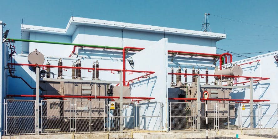
Figure 47 – Indoor CB, Bus coupler, Control room panels for indoor SF6 based switching cubicles
Go back to the Contents Table ↑
2.5 Commissioning
2.5.1 Charging Power Transformer, Auxiliary Power Supply
Connection of control room equipment, power transformer (Figures 48 and 49), substation auxiliary transformer (Figure 50) and back-up power source (usually outdoor silent type diesel generator (DG) set).
Activity causing Impact and Location: Erection, filling of oil and charging the power transformer.
(Location: Switchyard)
Impact of activity and its type: Leakage of transformer oil and sparking due to loose connections from standby power set.
(Type: Temporary)
Impact Mitigation: Concrete lined pits are erected to contain the oil. Firefighting equipment maintained in working order at site.
Work process: Transformer connectivity is done mostly trained personnel from the manufacturer who are adept at interconnections, wiring and
testing.
Figure 48 – Power transformers

Figure 49 – Power transformers

Figure 50 – Substation auxiliary transformer

Go back to the Contents Table ↑
2.5.2 Communication, Power Line Carrier Communication (PLCC)
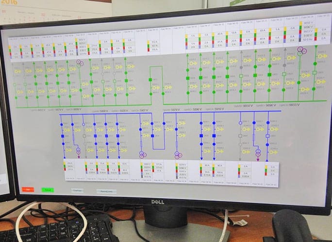
PLCC equipment for speech transmission, line protections, and data channels provides communications over power transmission lines. SCADA (Supervisory control and data acquisition) is a system operating with coded signals over communication channels.
Activity causing Impact and Location: Connectivity and internal wiring in Control room panels for bays (See Figure 51) Wave trap and other installations in the bus bar/bay are shown in Figure 52. SCADA system is shown in Figure 53. (Location: Control Room, Switch yard)
Impact of activity and its type: Remote operation of substation and line jeopardized due to faulty installation. (Type: Temporary)
Impact Mitigation: Proper safety protocols implemented while installation of communication equipment.
Work process: PLCC uses time-tested technology of communication via modulation of voice frequency over the power cable. SCADA is used to provide control system for remote operation.
Figure 51 – SCADA panels at substation
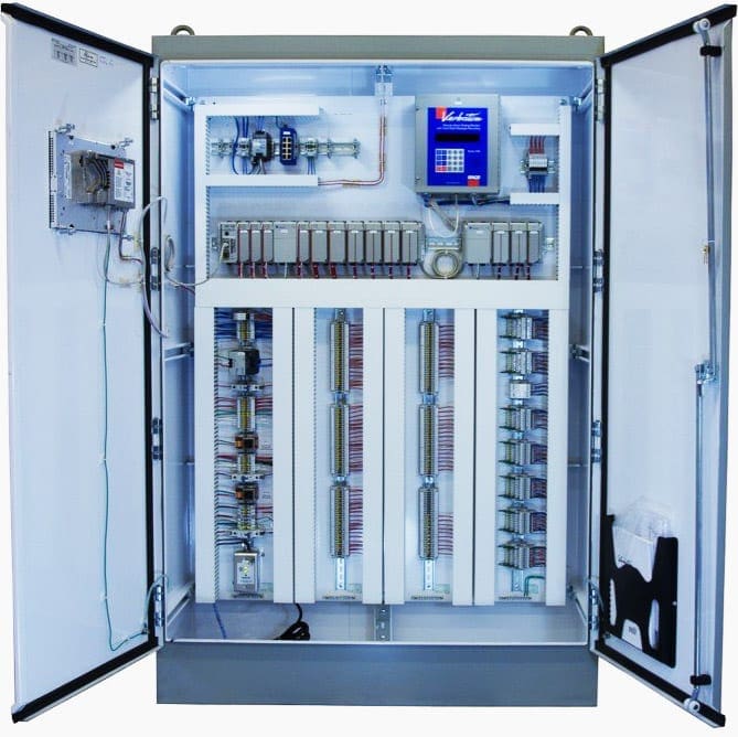
Figure 52 – PLCC equipment: Wave traps

Figure 53 – Supervisory control system of 110/10/6 kV substation
Go back to the Contents Table ↑
2.5.3 Connecting Terminating Lines Into Substation Equipment Restoration of Soil, Slope Stabilization
The connecting of incomer and outgoing lines is done manually using pulleys, ropes and winches to provide the correct distance within substation connections prescribed as per international IEC (International Electro-technical Commission) standards.
Activity causing Impact and Location: Connecting jumpers between the suspension clamps on incomer lines to the bus bar, and drop down to power transformer via isolators, CT, PT, CB etc. Connecting of cable spacers and other accessories on the power cable. (Location: Substation)
Impact of activity and its type: Improper connections, improper spacing and distance from nearby structures causing faults. Increase in soil runoff, soil erosion due to improper slopes, blockages in drains and slopes. terrestrial ecology, migratory birds. (Type: Temporary).
Impact Mitigation: Proper connectivity of jumpers and clamps to avoid short circuit faults. Ensure impact on human environment, health and safety norms are followed during erection and testing and commissioning. Restoration of soils, removal of blockages from drains, slope and gulley’s, cleaning of all construction material leftovers and proper green belt development.
Work process: A system of ropes and pulleys is used to manually provide specified spacers, clamps, vibration dampers etc. on the power cable. Testing and commissioning takes 2-3 days and involves modular tests on each aspect of transformer operation, operation of each switchgear, and running of normal operations using auxiliary power supply.
Figure 54 – Termination of incoming lines into bus bar

Figure 55 – Clamps, CC rings, etc.

Go back to the Contents Table ↑
3. Distribution Transformers (Below 33 kV)
Using 11 kV or 33 kV lines over longer distances increases the technical and commercial losses compared to 66 kV, or 132 kV lines. This factor limits the threshold usage of 33 kV or less voltage lines to shorter distances (say up to 30 kilometers) for distribution system.
Therefore, as a normal practice, all distribution transformers are connected to lines which are charged at 33 kV lines or below to the consumer end applications.
Mostly a small mechanized boom crane, otherwise it is manually unloaded and installed using chain and pulleys blocks.
3.1 Construction Practice, Their Environmental Impacts, Mitigation and Work Process
The Flow Chart in Figure 56 displays activities as they progress while constructing a distribution transformer (DTR). On the left are the “Steps” involved in the process of project implementation such as “Pre Construction, Facilities Setup, Construction, Erection, and Commissioning”.
The following steps are usually performed by the EPC contractor:
- Surveys, Alternate Analysis
- Temporary Worker Camp
- Unloading of material at site
- Digging Pits of Poles: Foundation pits, which are very small in this case are dug manually in both level and the hilly areas.
- Pole erection and concrete pouring in pole foundations: The poles are unloaded manually at the erection point. Foundation concrete mixture is usually made using a manual mixing machine and casted manually using ply-boards and/or wood casts.
- Erecting Distribution Transformer: DTR is usually brought to the site in trucks and can be normally lifted using Morris cable pulley.
- Connecting of terminating lines into DTR, Testing and Commissioning: The stringing of wires is done manually using pulleys, ropes and a manual winch to provide the correct sag prescribed for the wire and ambient conditions.
Figure 56 – Process Flow Chart for Construction of Distribution Transformer (DTR)

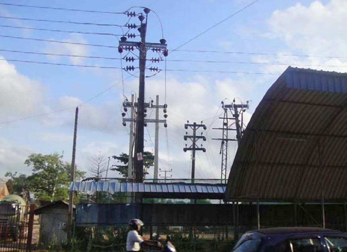
Figures 57, 58 and 59 shows three different types of distribution arrangements:
- Distribution switching substations where there is no transformers and a system of switches is used for isolating or sectionalizing the feeders;
- A fenced DTR facility atop bi-pole or four pole structure; and
- The ground 33/11 kV transformer to split the 11 kV feeder lines and also supply on-the-ground facility.
Figure 57 – Distribution switching substation (gantry structure)

Figure 58 – Distribution Transformer on concrete poles
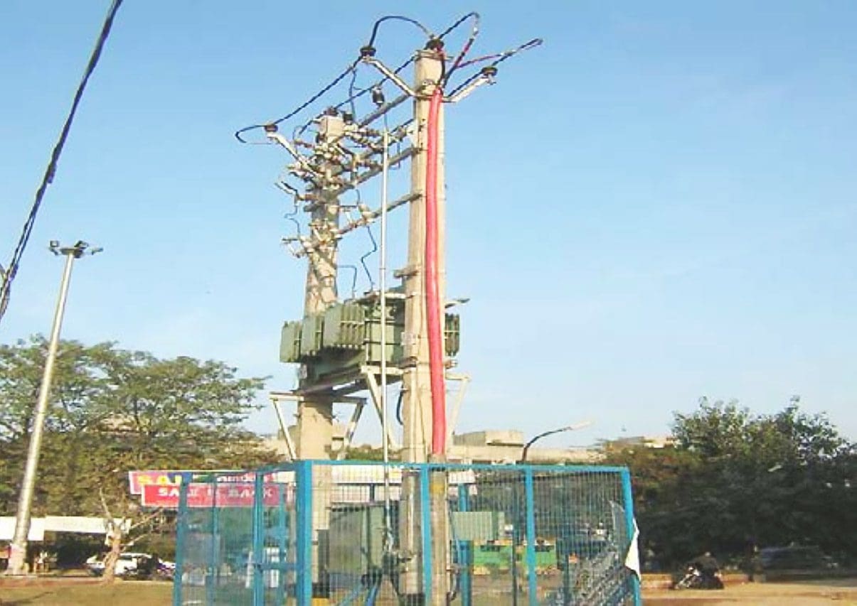
Figure 59 – 11 kV lines emanating from on-ground 33/11 kV transformer
Go back to the Contents Table ↑
Source: Handbook On Construction Techniques by Rajat Jain and Shotaro Sasaki


pleasant information
Good photos and high level overview – but light on earthing.soil surveys, commissioning , planning around 7long lead items( trafos) and design / selection of plant items. R2D3!
dear sir
I’m asking for an topic clarify the logistics & Transportation cost of power transformer and how accounted of the total cost of LPT in dimictic and international handling
i am ask for Electrical & Instrumentation , HVAC all equipment check list format pdf or excel format