The magnetic ballast

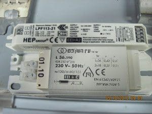
Fluorescent tubes and discharge lamps require the intensity of the arc to be limited, and this function is fulfilled by a choke (or magnetic ballast) placed in series with the bulb itself (see fig. 5 ).
This arrangement is most commonly used in domestic applications with a limited number of tubes. No particular constraint applies to the switches. Dimmer switches are not compatible with magnetic ballasts: the cancellation of the voltage for a fraction of the period interrupts the discharge and totally extinguishes the lamp.
The starter
The starter has a dual function: preheating the tube electrodes, and then generating an overvoltage to ignite the tube. This overvoltage is generated by the opening of a contact (controlled by a thermal switch) which interrupts the current circulating in the magnetic ballast.
During operation of the starter (approx. 1 s), the current drawn by the luminaire is approximately twice the nominal current.
Compensation
Since the current drawn by the tube and ballast assembly is essentially inductive, the power factor is very low (on average between 0.4 and 0.5). In installations consisting of a large number of tubes, it is necessary to provide compensation to improve the power factor.
Possible layouts
For large lighting installations, centralized compensation with capacitor banks is a possible solution, but more often this compensation is included at the level of each luminaire in a variety of different layouts (see fig. 6 ). The compensation capacitors are therefore sized so that the global power factor is greater than 0.85.
In the most common case, that of parallel compensation, its capacity is on average 1 μF for 10 W of active power, for any type of lamp. However, this compensation is incompatible with dimmer switches.
Constraints affecting compensation
The layout for parallel compensation creates constraints on ignition of the lamp. Since the capacitor is initially discharged, switch-on produces an overcurrent. An overvoltage also appears, due to the oscillations in the circuit made up of the capacitor and the power supply inductance.
- Assuming an assembly of 50 fluorescent tubes of 36 W each:
– total active power: 1800 W,
– apparent power: 2 kVA,
– total rms current: 9 A,
– peak current: 13 A.
- With:
– a total capacity: C = 175 μF,
– a line inductance (corresponding to a shortcircuit current of 5 kA): L = 150 μH.
The maximum peak current at switch-on equals:

The theoretical peak current at switch-on can therefore reach 27 times the peak current during normal operation.
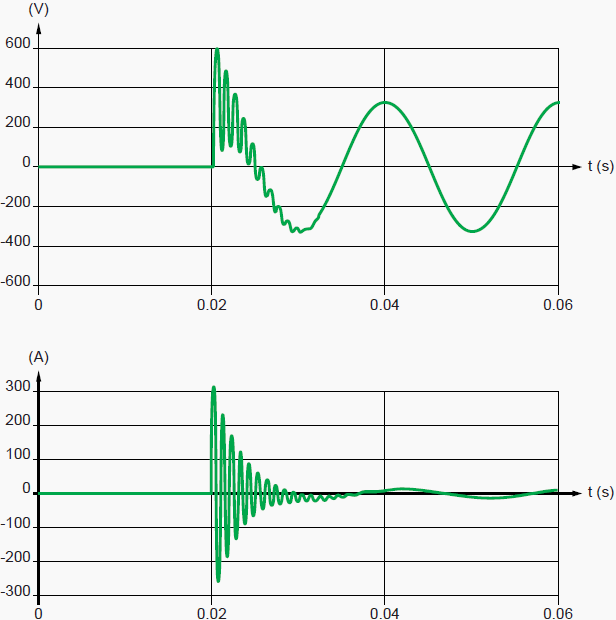
The shape of the voltage and current at ignition is given in figure 7 for switch closing at the line supply voltage peak. There is therefore a risk of contact welding in electromechanical control devices (remote control switch, contactor, circuit-breaker) or destruction of solid state switches with semiconductors.
In reality, the constraints are usually less severe, due to the impedance of the cables.
![Fig. 6: the various compensation layouts: a] parallel; b] series; c] dual series also called “duo” and their fields of application. Fig. 6: the various compensation layouts: a] parallel; b] series; c] dual series also called “duo” and their fields of application.](https://electrical-engineering-portal.com/wp-content/uploads/fig-6-the-various-compensation-layouts.gif)


” Power supply of luminaires with magnetic ballasts ” … Spectacular, concise, simple. Only brigth mind can do it.