
Estimated Study Time: 19 minutes
Protection functions and communications
First, I would like to make a note that there are many essentials when we speak about power systems in general. The main relay protection functions (overcurrent, directional, differential, distance, etc.) and network communication systems (SCADA, RTUs, digital and analog inputs and outputs, IEC 61850, etc.) are briefly explained in this technical article.
 The essentials of power systems: Relay protection and communication systems
1. Protection systems
Protection equipment is necessary to detect and isolate faults from the system. Protection relays detect faults by comparing the quantity (and angles in some cases) of the primary circuit current or voltage to a pre-determined setting. This comparison is done electromechanically for induction-type relays and digitally or electronically for digital or static relays.
The main protection functions for distribution and transmission lines are briefly explained below:
1.1 Overcurrent protection
The relay starts to operate (pick up) when current magnitude exceeds the preset current setting. Overcurrent can be detected in phase conductors, neutral conductors and/or the earth return path:
Phase-overcurrent or “overcurrent” protection is where current in a phase conductor is measured.
Ground-overcurrent or “earth fault” protection is used to detect earth faults whereby:
- The current in a specific neutral or earth conductor is measured and/or
- The residual current of the phase conductors of a 3 phase system is measured. This is achieved by measuring the “summed” current of the parallel connection of all phase CT’s, or is calculated within the relay itself, (applicable only to digital relays).
The residual current in a typical distribution HV network is zero during normal conditions, even with extreme load unbalance. This is due to distribution transformer primary winding and earthing configuration. Sensitive settings can therefore be applied to earth fault relay, typically, a setting of 10>20% of the nominal CT secondary current is used.

It is possible for a residually connected relay to operate when a high-resistance joints is present in one phase of a multiple parallel circuit.
Ground-overcurrent (earth fault) relays often use a definite-time characteristic only, as the earth fault current magnitude does not vary so greatly between two relaying points on a given network.
More about overcurrent relay protection you can learn from this Thesis:
1.2 Directional overcurrent protection
Same as previous, with the addition that the direction of a fault can be known by comparison of the primary circuit voltage and current. Directional overcurrent is widely used in protection of ring or parallel feeders, where fault current can flow in either direction depending on the location of the fault and supply source.
Directional relays that look back directly into a source can be set sensitively, as current flowing in this direction will be abnormal, and thus considered a fault.
Let’s see an example (Figure 3) where directional IEDs are called for is in a ring main feeder system, as depicted in Figure 3. Such a system allows supply to be maintained to all loads in spite of a fault on any section of the feeder. A fault in any section causes only the CBs associated with that section to trip.
Power then flows to the load through the alternative path. The directional IEDs and their tripping direction are indicated by arrows in the diagram. The doubleended arrows indicate non-directional IEDs, as these will trip with currents flowing in either direction.
More about earth/phase directional overcurrent you can read here:
Using earth & phase directional protection where power flow direction might change
1.3 Differential protection
Differential protection compares the current entering the protected circuit (or zone) to the current leaving the zone. What goes in must come out! A zone is bounded by measuring CT’s at the terminals of the protected circuit. Where the terminals are some appreciable distance apart, then a communications channel or pilot wire is required between ends for differential comparison, logic and inter-tripping facilities.
There are many various patented techniques available to perform differential comparison and intertripping.
As differential protection only operates for faults within a zone of protection, there is no requirement to consider the operation times of protection outside the zone; instantaneous operation is therefore often applied to differential protection.
In short, the sum of the currents flowing in essentially equals the sum of the currents flowing out during normal operation.
More about differential protection you can learn here:
Differential protection – Proven technique for more than 50 years
1.4 Distance protection
Distance relaying principles are based on impedance measurement and so require the values of primary circuit voltage and current for any instant time. The impedance of any given circuit is a fixed quality; if the impedance measured by the relay has decreased to some value below a predetermined setting, then a fault is assumed on the circuit and tripping can be initiated.
IMPORTANT! – On overhead line HV systems, many faults, particularly earth faults may be transient ones, hence earth fault and overcurrent protection systems may be associated with auto reclose relays. These relays automatically reclose the circuit breakers after a short pre-determined time and these usually lock out after a set number of unsuccessful attempts.
Overcurrent relays have been used generally for ground-fault primary and back-up protection, but there is a growing trend toward distance relays for ground faults also.
Recommended reading related to distance relay protection:
Eight most important distance relay characteristics (based on impedance comparison)
2. Communication systems
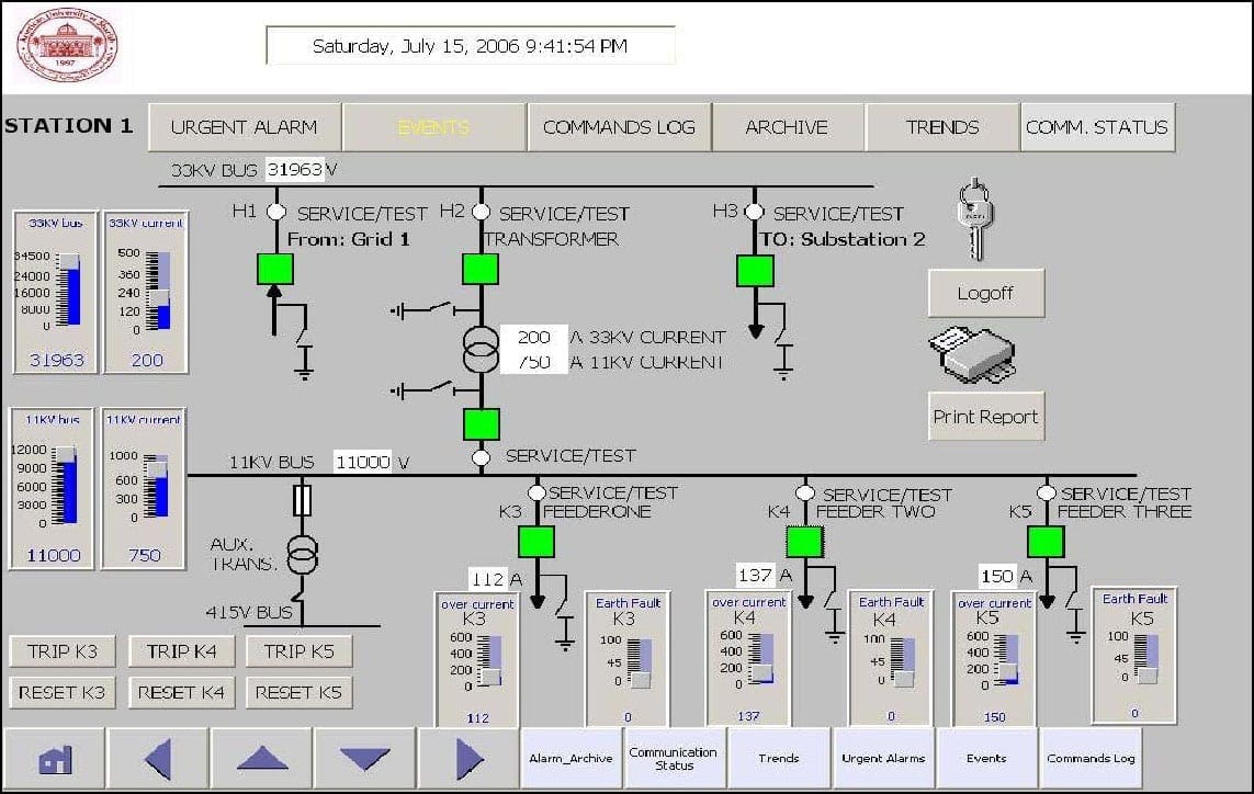
Remote control and indications of substations and field equipment are vital in ensuring safe, efficient and effective operation of an electrical distribution network. This was the primary objective for the development of SCADA systems, (Supervisory Control And Data Acquisition).
As the name implies, the SCADA systems main functions are to provide remote control of remote devices and to return the status, alarm and system operating data from remote devices.
Remote control is generally required from one or more strategically located control centres. The main control point is often known as the Network Control Centre, (NCC).
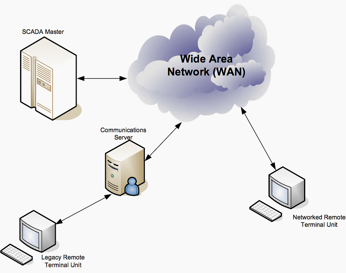
The SCADA master station which generally resides at the NCC, communicates to Remote Terminal Units (RTU’s) located at substations and on field equipment such as pole mount Autoreclosers. The SCADA master interrogates the RTU’s over a communications network.
The medium for the communications networks can take many different forms; the most widely used are radio, pilot or supervisory wire and fibre-optic.
2.1 Supervisory and control functions
The SCADA system is a general hardware and software concept providing a flexible set of functions. The actual use of the SCADA system is specified by parameters defined in the database. This brings down system costs, increases system reliability through its well-proven design, and makes project development and implementation safe.
It further constitutes a basis for implementing more advanced functions. They provide for further development of the control system once it has been put into operation.
This is a basic requirement since it must be possible to add new power system components which are going to be monitored and controlled by the control system.
2.1.1 Data Acquisition
The basic information with regard to the power system is collected by equipment in the various substations and power plants. The distributed control system equipment enables remote data acquisition. Data may also be entered manually or calculated. These data are treated exactly like the automatically collected data.
Data acquisition operation is required to:
- Read power system measurement data from RTUs into the control computer under program control.
- Detect and handle data error conditions due to RTU and communication system malfunctions and noise.
- Scale and convert analogue data into binary form directly usable by the computer programs.
- Interface with database manager (DBM) that generates data base addresses, and store data in database.
- Store only error free data, quality indicators should be set to denote error conditions.
- Complete the scan in minimum possible time before the next scan begins.
2.2 Communication network
The communications network is intended to provide the means by which data can be transferred between the central host computer servers and the field-based RTUs. The Communication Network refers to the equipment needed to transfer data to and from different sites. The medium used can either be cable, telephone or radio.
The use of cable is usually implemented in a factory. This is not practical for power systems covering large geographical areas because of the high cost of the cables, conduits and the extensive labor in installing them. The use of telephone lines (i.e., leased or dial-up) is a more economical solution for systems with large coverage. The leased line is used for systems requiring on-line connection with the remote stations. This is expensive since one telephone line will be needed per site.
Historically, SCADA networks have been dedicated networks. However, with the increased deployment of office LANs and WANs as a solution for interoffice computer networking, there exists the possibility to integrate SCADA LANs into everyday office computer networks. The foremost advantage of this arrangement is that there is no need to invest in a separate computer network for SCADA operator terminals.
In addition, there is an easy path to integrating SCADA data with existing office applications, such as spreadsheets, work management systems, data history databases, Geographic Information System (GIS) systems, and water distribution modeling systems.
It would be good to read the following technical article, since it describes the most important things in substation automation,
Five Terms You MUST Be Familiar With: SCADA, DCS, PLC, RTU and Smart Instrument
Control centre communications can also be achieved with Intelligent Electronic Devices (IED’s) such as digital relays via serial communications linked to the RTU or to the SCADA master itself. The main benefit of this is that event data, indication and control points available within the IED can be accessed remotely via SCADA.
2.3 IEC 61850
At the end, we must mention the Standard IEC 61850. Sharing real-time data becomes a dominant task for any successive system operation. In a substation, the real-time data needs to be shared speedily and accurately among the substation devices as well as with other energy subsystems.
This concept has generated a demand to integrate and consolidate IEDs. This task may require a standardized communications language among devices in order to facilitate interfaces, since the existing solutions have reached their limits.
IEC 61850 considers the various aspects that are common at the substation site, such as data models, communication solutions, engineering and conformity over the channel. Although organizing the data in terms of applications by means of syntax and semantics within the devices, they did not specify it.
The main aspect that IEC 61850 adopts is the associated architectural construct, “abstracting” the data object’s definition and its services. These data objects and their associated services are abstracted independently from any underlying protocol, which supports a comprehensive set of substation functions and provides strong services in order to facilitate the energy system’s communication.
Therefore, the IEC 61850 specification can be encapsulated according to three major focusing issues:
Issue #1 – Standardizing the available information (the data object model), substation functions (the functional model) and the IEDs name, thereby providing the IEDs with a shared vocabulary that supports the intended semantic meaning.
Issue #2 – Standardizing different ways of the accessing the scheme for the available data’s abstract communication services interface (ACSI). These ways are defined as services. Further, specifying the mapping scheme according to the communication services and the data according to a number of protocols.
Issue #3 – Defined a language eXtendable Markup Language (XML) implemented to describe all the configuration information exchanged between the IEDs, the network and the power system.
Further reading:
Sources: IDAHO Power, Victorian Electricity Supply Industry, Reliability and Performance of IEC 61850 by M. Mekkanen
Related electrical guides & articles


Edvard Csanyi
Hi, I'm an electrical engineer, programmer and founder of EEP - Electrical Engineering Portal. I worked twelve years at Schneider Electric in the position of technical support for low- and medium-voltage projects and the design of busbar trunking systems.I'm highly specialized in the design of LV/MV switchgear and low-voltage, high-power busbar trunking (<6300A) in substations, commercial buildings and industry facilities. I'm also a professional in AutoCAD programming.
Profile: Edvard Csanyi

I am not very certain on the relevance of the RTU since its function is to interface with the power system equipment signals a function that is easily accomplished by a protection relay. You can connect the protection relay to a controller or SCADA via a LAN or WAN link. So does the RTU still have a place in the modern power system automation network architecture given the powerful communication capabilities of the protection relays on the market?
thanks . i have equation .
RTU maintenance eng. shouid be communication eng. or protection eng. ?
Thank you for the kind presentation.
This site has taught me more than what i learnt throughout my stay in the university.
Keep it up sir.
I wish you can put me through power engineering economics.
Congratulations for your work and effort to share knowledge in the science of Electrical Power Systems. Greetings from Brazil!
Thank you very much Julio! Be well and safe.
I have been with this site for sometimes the EPP has been updating power systems engineers on the dynamics of the system with current Millenium operation.
Thank you.
You’re welcome Atiku. I’m glad you like our work.