
Estimated Study Time: 54 minutes
Sensors that scream and flash
Modern transformers are like cars full of sensors and electronics that scream and flash when something goes wrong. Most of the time, that’s very good and useful, but it could be irritating in case of repetitive false alarms that need further investigation. This article is dedicated to these transformer sensors, precisely, fittings and accessories that make transformer operation safer and more secure.
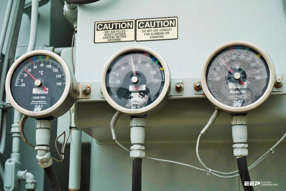 Often incorrectly specified and ordered: Power transformer fittings and accessories (on photo: Oil Temperature Indicator (OTI) and Winding Temperature Indicator (WTI) Gauges; credit: dynamicratings.com)
Technical specification for ordering transformer fittings and accessories could be critical, especially in case of replacement or spare parts for an old existing transformer.
All of the external parts and fittings installed on the transformer tank are necessary for the transformer to operate satisfactorily while it is in use. In this technical article, a few essential fittings that must be present on various transformers are described. However, large rating transformers are also equipped with a few extra fittings and accessories depending on the rating in order to meet the necessary specifications.
This article discusses various sensors and extras that are typically included with power transformers in the 132 kV and higher class.
Due to the commercial availability of components with various features and the lack of any authoritative guidelines, users frequently struggle to clearly specify the products that would satisfy their long-term requirements.
Therefore, efforts have been made to broadly align details of the items covered herein with these standards and some other available references.
It should be noted that the list is not all-inclusive. Cooing fans, oil/water pumps, pressure gauges, RTDs, valves, breathers, rollers, earthing terminals, heat exchangers, unit coolers, etc. are some of the items that are not currently covered here but can be found in several other technical articles that have already been published.
- Temperature Indicators:
- Fibre Optic Sensors
- Gas & Oil Actuated Relay (Buchholz Relay)
- Pressure Relief Valve
- Magnetic Oil Level Gauge
- Oil / Water Flow Indicators
- Air Cell or Flexi-Separator
- Conservator Protection Relay / Aircell Puncture Detection Relay
- Removable Radiators for Oil-immersed Transformers
- Automatic Voltage Regulating Relay (AVR)
- Transformer Nitrogen Injection Fire Prevention System
1. Temperature Indicators
1.1 Oil Temperature Indicator (OTI)
Oil temperature indicator is installed in the marshaling box (in transformer yard) and used to measure the temperature of top oil in transformer.
Principle of Operation: – The top oil temperature of oil immersed power transformer is sensed by measuring system based on volumetric expansion of liquid proportional to rise in temperature. A sensing bulb, measuring bellow and a small bore capillary connecting the two form the measuring system which is filled with liquid.
Complete ambient temperature compensation on sensing bulb & line / capillary is provided with a second bellow / compensating bellow and a capillary that terminates at head of the sensing bulb. The liquid filled inside this responds to ambient temperature changes. The measuring and compensating bellows are linked in such a way that they cancel out.
Thus, the net measuring bellow output is dependent only on the sensing bulb temperature and not on ambient temperature.
Datasheet – Oil Temperature Indicator (OTI)
Notes:
- 4 to 20mA correspond to 0 to 150 °C respectively.
- In case of failure of analog type indicator (Variant-2), PSU will give continuous 4 to 20mA output
Figure 1 – Bulb fitting arrangement for variant 1 and 2 of Oil Temperature Indicator (OTI)
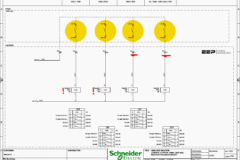
Figure 2 – Standard Wiring Diagrams of Oil Temperature Indicator (OTI)
Any of the above two terminal configurations can be selected as per requirement. The contact position shown above is under normal operating condition of OTI.
Selection Criteria: – 4 to 20 mA output required or not for remote/SCADA indication
Routine Tests:
- Mount the temperature Indicator on Test Stand Vertically,
- Connect as per scheme diagram.
- Micro switch terminals with multimeter / Buzzer (Continuity test).
- “Thermal image” bellow heater terminal (CT Terminal) with current source
- Close the Top cover
- Set oil bath temperature at 40°C, with reference to the standard Thermometer.
- Loosen union screw and remove the union (Ensure minimum immersion length of 140 mm). Immerse sensing bulb in hot oil bath.
- Record the instrument temperature after 5 minutes, the bath reaches the steady temperature.
- Increase the oil bath temperature in steps of 20°C and record the temperature of the instrument after 5 minutes when the bath reaches the steady state temperature.
- Simultaneously observe and record the switch operation (ON) as instrument temperature rises.
- Remove the sensing bulb from oil bath and keep in till the instrument reading reaches the ambient temperature.
- Simultaneously observe and record the switch operation (OFF) as instrument temperature decreases (To check switch differential)
- Insulation Test (2 kV between contact and earth)
Installation & Pre-commissioning Checks:
- Before installation, check for possible damages from transport handling.
- Do not carry the instrument by holding the capillary line.
- Ensure not to twist the capillary line while unpacking, storage or installation.
- Avoid sharp bends of capillary line and allow minimum of 50 mm bending radius.
- Keep the instrument on mounting surface and fix it.
- Make sure that instrument is mounted in a vertical position.
- Clamp the capillary line along its entire length at approximately 500 mm intervals. The excess length can be wound in spiral with minimum diameter of 100 mm.
- Oil is to be filled in the pocket. Insert the sensing bulb through union/ pocket/ flange (insert fully), tighten nut to optimum level. Ensure min. immersion length 140 mm.
- Care must be taken that, Sensing bulb is not damaged while tightening.
- In case of further transport or storage, wind the armor and pack the instrument in the same way as received from the supplier.
- Check the connection as per wiring diagram before commissioning.
- Cable entry should be through cable gland to avoid dust entering
- Top cover should be put in place and tighten properly to avoid dust. Ensure that the maximum pointer is positioned after the indicating pointer.
- Make sure there are no loose connections.
- Test knob, if provided externally, should be locked properly after testing.
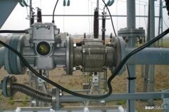
Figure 3 – Transformer winding and oil temperature indicators

Go back to the Contents Table ↑
1.2 Winding Temperature Indicator (WTI)
Winding temperature indicator (WTI) is installed in the marshaling box (in transformer yard) and used to measure the hotspot temperature of the winding.
Principle of Operation: – The top oil temperature of Oil Immersed Power transformer is sensed by measuring system based on volumetric expansion of liquid proportional to rise in temperature. A Sensing bulb, measuring bellow and a small bore capillary connecting the two form the measuring system which is filled with liquid.
When the sensing bulb is exposed to rise in temperature, the liquid inside expands proportionately causing the bellows to expand and drive the linkages for indication and separately, linkages & disc for switch operation. This system is self contained and does not depend on any outside power source for its operation.
Complete ambient temperature compensation on sensing bulb & line/capillary is provided with a second bellow/compensating bellow and a capillary that terminates at head of the sensing bulb. The liquid filled inside this responds to ambient temperature changes. The measuring and compensating bellows are linked in such a way that they cancel out.
Thus, the net measuring bellow output is dependent only on the sensing bulb temperature and not on ambient temperature.
The temperature in the hottest part of the winding or hotspot temperature is displayed directly by the instrument. Thus, the instrument functions as a winding temperature indicator. The time constant of the temperature rise will be 63.7% of final temperature rise within 7-8 minutes.
Since the thermal time constant of the heater coil is nearly the same as the transformer winding, the instrument simulates closely the actual temperature of the winding in relation to time.
Related electrical guides & articles


Edvard Csanyi
Hi, I'm an electrical engineer, programmer and founder of EEP - Electrical Engineering Portal. I worked twelve years at Schneider Electric in the position of technical support for low- and medium-voltage projects and the design of busbar trunking systems.I'm highly specialized in the design of LV/MV switchgear and low-voltage, high-power busbar trunking (<6300A) in substations, commercial buildings and industry facilities. I'm also a professional in AutoCAD programming.
Profile: Edvard Csanyi
