
Estimated Study Time: 27 minutes
Transformer protection methods
The problems relating to transformer temperature rise above an assumed maximum ambient temperature require some means of protection. Let’s summarize the problems and the possible forms of transformer protection that may be used.
 Power transformer protection methods & relay schemes
The considerations for a transformer protection vary with the application and importance of the power transformer.
It is normal for a modern relay to provide all of the required protection functions in a single package, in contrast to electromechanical types that would require several relays complete with interconnections and higher overall CT burdens.
Table 1 – Transformer fault types/protection methods
| No. | Fault Type | Protection used |
| 1. | Primary winding Phase-Phase fault | Differential; Overcurrent |
| 2. | Primary winding Phase-Earth fault | Differential; Overcurrent |
| 3. | Secondary winding Phase-Phase fault | Differential |
| 4. | Secondary winding Phase-Earth fault | Differential; Restricted Earth Fault (REF) |
| 5. | Interturn Fault | Differential; Buchholz |
| 6. | Core Fault | Differential; Buchholz |
| 7. | Oil tank Fault | Differential; Buchholz; Tank Earth |
| 8. | Overfluxing | Overfluxing |
| 9. | Overheating | Thermal |
The following sections in this article provide more detail on the individual protection methods. Note that combined differential and REF, overfluxing, tank-earth and oil/gas protection are described in the next part of this article.
- Transformer overcurrent protection
- Restricted earth fault protection (REF)
- Differential protection
- How to preserve differential protection during magnetizing inrush conditions
1. Transformer overcurrent protection
Fuses may adequately protect small transformers, but larger ones require overcurrent protection using a relay and CB, as fuses do not have the required fault breaking capacity.
1.1 Fuses
Fuses commonly protect small distribution transformers typically up to ratings of 1MVA at distribution voltages. In many cases no circuit breaker is provided, making fuse protection the only available means of automatic isolation.
The fuse must have a rating well above the maximum transformer load current to withstand the short duration overloads that may occur. Also, the fuses must withstand the magnetising inrush currents drawn when power transformers are energized.
Table 1 shows typical ratings of fuses for use with 11kV transformers.
Table 2 – Typical fuse ratings for use with distribution transformers
| Transformer Rating | Fuse | ||
| kVA | Full Load Current (A) | Rated Current (A) | Operating Time at 3 × Rating (s) |
| 100 | 5.25 | 16 | 3.0 |
| 200 | 10.5 | 25 | 3.0 |
| 315 | 15.8 | 36 | 10.0 |
| 500 | 26.2 | 50 | 20.0 |
| 1000 | 52.5 | 90 | 30.0 |
This table should be taken only as a typical example. Considerable differences exist in the time characteristics of different types of HRC fuses. Furthermore grading with protection on the secondary side has not been considered.
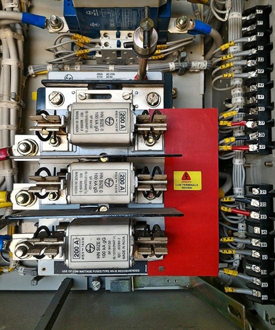
Figure 1 – HRC fuses
1.2 Overcurrent relays
With the advent of ring main units incorporating SF6 circuit breakers and isolators, protection of distribution transformers can now be provided by overcurrent trips.
For example, tripping controlled by time limit fuses connected across the secondary windings of in-built current transformers) or by relays connected to current transformers located on the transformer primary side.
Overcurrent relays are also used on larger transformers provided with standard circuit breaker control.
A high-set instantaneous relay element is often provided, the current setting being chosen to avoid operation for a secondary short circuit.
This enables high-speed clearance of primary terminal short circuits.
Figure 2 – Overcurrent relay arrangement with CT’s, including 50/51N
Watch Video – Characteristics of Overcurrent Relay
2. Restricted earth fault protection (REF)
Conventional earth fault protection using overcurrent elements fails to provide adequate protection for transformer windings. This applies particularly to a star-connected winding with an impedance-earthed neutral.
For the high-impedance type, the residual current of three line current transformers is balanced against the output of a current transformer in the neutral conductor. In the biased low-impedance version, the three phase currents and the neutral current become the bias inputs to a differential element.
The system is operative for faults within the region between current transformers, that is, for faults on the star winding in question. The system remains stable for all faults outside this
zone.
Figure 3 – Restricted earth fault protection for a star winding
The gain in protection performance comes not only from using an instantaneous relay with a low setting, but also because the whole fault current is measured, not merely the transformed component in the HV primary winding (if the star winding is a secondary winding).
Hence, although the prospective current level decreases as fault positions progressively nearer the neutral end of the winding are considered, the square law which controls the primary line current is not applicable, and with a low effective setting, a large percentage of the winding can be covered.
This is an improvement compared with the performance of systems that do not measure the neutral conductor current.
Figure 4 – Earth fault current in resistance-earthed star winding
Earth fault protection applied to a delta-connected or unearthed star winding is inherently restricted, since no zero sequence components can be transmitted through the transformer to the other windings.
Both windings of a transformer can be protected separately with restricted earth fault protection, thereby providing high-speed protection against earth faults for the whole transformer with relatively simple equipment.
A high impedance relay is used, giving fast operation and phase fault stability.
3. Differential protection
The restricted earth fault schemes described above depend entirely on the Kirchhoff principle that the sum of the currents flowing into a conducting network is zero.
Figure 5 shows the principle. Current transformers on the primary and secondary sides are connected to form a circulating current system.
Figure 5 – Principle of transformer differential protection
3.1 Basic considerations for transformer differential protection
In applying the principles of differential protection to transformers, a variety of considerations have to be taken into account.
These include:
- Correction for possible phase shift across the transformer windings (phase correction)
- The effects of the variety of earthing and winding arrangements (filtering of zero sequence currents)
- Correction for possible unbalance of signals from current transformers on either side of the windings (ratio correction)
- The effect of magnetizing inrush during initial energization
- The possible occurrence of overfluxing
Digital numerical relays implement ratio and phase correction in the relay software instead, thus enabling most combinations of transformer winding arrangements to be catered for, irrespective of the winding connections of the primary CTs.
This avoids the additional space and cost requirements of hardware interposing CTs.
Further Studying – Mastering stability test of power transformer: Differential and Restricted Earth Fault (REF) protection
3.2 Line current transformer primary ratings
Line current transformers have primary ratings selected to be approximately equal to the rated currents of the transformer windings to which they are applied. Primary ratings will usually be limited to those of available standard ratio CTs.
3.3 Phase Correction
Correct operation of transformer differential protection requires that the transformer primary and secondary currents, as measured by the relay, are in phase. If the transformer is connected delta/star, as shown in Figure 6, balanced three-phase through current suffers a phase change of 30°.
If left uncorrected, this phase difference would lead to the relay seeing through current as an unbalanced fault current, and result in relay operation. Phase correction must be implemented.
Figure 6 – Differential protection for two-winding delta/star transformer
Electromechanical and static relays use appropriate CT/ICT connections to ensure that the primary and secondary currents applied to the relay are in phase. For digital and numerical relays, it is common to use starconnected line CTs on all windings of the transformer and compensate for the winding phase shift in software.
Depending on relay design, the only data required in such circumstances may be the transformer vector group designation. Phase compensation is then performed automatically.
Phase compensation and associated relay data entry requires more detailed consideration in such circumstances. Rarely, the available phase compensation facilities cannot accommodate the transformer winding connection, and in such cases interposing CTs must be used.
Further Studying – Three-phase basics and terms that students often mix
3.4 Filtering of zero sequence currents
It is essential to provide some form of zero sequence filtering where a transformer winding can pass zero sequence current to an external earth fault. This is to ensure that out-of-zone earth faults are not seen by the transformer protection as an in-zone fault.
For digital and numerical relays, the required filtering is applied in the relay software. Table 3 summarizes the phase compensation and zero sequence filtering requirements.
Table 3 – CT connections for power transformers of various vector groups
| Transformer Connection | Transformer Shift | Clock Face Vector | Phase Compensation Required | HV Zero Sequence Filtering | LV Zero Sequence Filtering | |
| Yy0 | 0° | 0 | 0° | Yes | Yes | |
| Zd0 | Yes | |||||
| Dz0 | Yes | |||||
| Dd0 | ||||||
| Yz1 | Zy1 | −30° | 1 | 30° | Yes | Yes |
| Yd1 | Yes | |||||
| Dy1 | Yes | |||||
| Yy6 | −180° | 1 | 180° | Yes | Yes | |
| Zd6 | Yes | |||||
| Dz6 | Yes | |||||
| Dd6 | ||||||
| Yz11 | Zy11 | 30° | 11 | −30° | Yes | Yes |
| Yd11 | Yes | |||||
| Dy11 | Yes | |||||
| YyH | YzH | (H/12) × 360° | Hour ‘H’ | −(H/12) × 360° | Yes | Yes |
| YdH | ZdH | Yes | ||||
| DzH | DyH | Yes | ||||
| DdH | ||||||
3.5 Ratio correction
Correct operation of the differential element requires that currents in the differential element balance under load and through fault conditions.
As the primary and secondary line CT ratios may not exactly match the transformer rated winding currents, digital/numerical relays are provided with ratio correction factors for each of the CT inputs.
If the transformer is fitted with a tap changer, line CT ratios and correction factors are normally chosen to achieve current balance at the mid tap of the transformer.
It is necessary to ensure that current mismatch due to off-nominal tap operation will not cause spurious operation.
Suggested Course – Transformer Differential Protection Course: Understanding Schematics, Relay Settings and Testing
Transformer Differential Protection Course: Understanding Schematics, Relay Settings and Testing
3.6 Bias setting
Bias is applied to transformer differential protection for the same reasons as any unit protection scheme – to ensure stability for external faults while allowing sensitive settings to pick up internal faults.
The situation is slightly complicated if a tap changer is present.
Some relays use a bias characteristic with three sections, as shown in Figure 7.
The first section is set higher than the transformer magnetizing current. The second section is set to allow for off-nominal tap settings, while the third has a larger bias slope beginning well above rated current to cater for heavy through-fault conditions.
Figure 7 – Typical bias characteristic
3.7 Transformers with multiple windings
The unit protection principle remains valid for a system having more than two connections, so a transformer with three or more windings can still be protected by the application of the above principles.
When the power transformer has only one of its three windings connected to a source of supply, with the other two windings feeding loads, a relay with only two sets of CT inputs can be used, connected as shown in Figure 8(a). The separate load currents are summated in the CT secondary circuits, and will balance with the infeed current on the supply side.
Schemes shown are single phase for the sake of simplicity.
Figure 8a – Differential protection arrangements for three-winding transformer (one power source)
When more than one source of fault current infeed exists, there is a danger in the scheme of Figure 8(a) of current circulating between the two paralleled sets of current transformers without producing any bias.
It is therefore important a relay is used with separate CT inputs for the two secondaries – Figure 8(b).
Figure 8b – Differential protection arrangements for three-winding transformer (three power sources)
When the third winding consists of a delta-connected tertiary with no connections brought out, the transformer may be regarded as a two winding transformer for protection purposes and protected as shown in Figure 8(c).
Figure 8c – Differential protection arrangements for three-winding transformer with unloaded delta tertiary
4. How to preserve differential protection during magnetizing inrush conditions?
The magnetizing inrush phenomenon produces current input to the energized winding which has no equivalent on the other windings. The whole of the inrush current appears, therefore, as unbalance and the differential protection is unable to distinguish it from current due to an internal fault.
Methods of delaying, restraining or blocking of the differential element must therefore be used to prevent mal-operation of the protection.
Watch Video – Magnetic inrush current explained in detail
4.1 Time delay
Since the phenomenon is transient, stability can be maintained by providing a small time delay. However, because this time delay also delays operation of the relay in the event of a fault occurring at switch-on, the method is no longer used.
4.2 Harmonic restraint
The inrush current, although generally resembling an in-zone fault current, differs greatly when the waveforms are compared. The difference in the waveforms can be used to distinguish between the conditions.
As stated before, the inrush current contains all harmonic orders, but these are not all equally suitable for providing bias.
The proportion of second harmonic varies somewhat with the degree of saturation of the core, but is always present as long as the uni-directional component of flux exists. The amount varies according to factors in the transformer design.
Normal fault currents do not contain second or other even harmonics, nor do distorted currents flowing in saturated iron cored coils under steady state conditions.
The output current of a current transformer that is energized into steady state saturation will contain odd harmonics but not even harmonics.
However, should the current transformer be saturated by the transient component of the fault current, the resulting saturation is not symmetrical and even harmonics are introduced into the output current. This can have the advantage of improving the through fault stability performance of a differential relay.
The second harmonic is therefore an attractive basis for a stabilizing bias against inrush effects, but care must be taken to ensure that the current transformers are sufficiently large so that the harmonics produced by transient saturation do not delay normal operation of the relay. The differential current is passed through a filter that extracts the second harmonic.
This component is then applied to produce a restraining quantity sufficient to overcome the operating tendency due to the whole of the inrush current that flows in the operating circuit.
By this means a sensitive and high-speed system can be obtained.
Watch Video – Harmonic restraint differential relay
4.3 Inrush Detection Blocking – Gap Detection Technique
Another feature that characterizes an inrush current can be seen from Figure 9 where the two waveforms (c) and (d) have periods in the cycle where the current is zero.
The minimum duration of this zero period is theoretically one quarter of the cycle and is easily detected by a simple timer T1 that is set to 1/4f seconds.
Figure 9 – Transformer magnetizing inrush
Figure 10 shows the circuit in block diagram form. Timer T1 produces an output only if the current is zero for a time exceeding 1/4f seconds. It is reset when the instantaneous value of the differential current exceeds the setting reference.
As the zero in the inrush current occurs towards the end of the cycle, it is necessary to delay operation of the differential relay by 1/f seconds to ensure that the zero condition can be detected if present. This is achieved by using a second timer T2 that is held reset by an output from timer T1.
Some numerical relays may use a combination of the harmonic restraint and gap detection techniques for magnetizing inrush detection.
Figure 10 – Block diagram to show waveform gap-detecting principle
Keep reading in the next part:
- Combined differential and restricted earth fault schemes
- Application when an earthing transformer is connected within the protected zone
- Overfluxing protection
- Tank-earth protection
- Oil and gas protection devices
- Oil pressure relief devices
- Sudden pressure rise relay
- Buchholz protection
Power transformer protection relaying (combined differential & restricted earth fault)
Reference: Network protection and automation guide by (ex) Alstom Grid, now General Electric
Related electrical guides & articles


Edvard Csanyi
Hi, I'm an electrical engineer, programmer and founder of EEP - Electrical Engineering Portal. I worked twelve years at Schneider Electric in the position of technical support for low- and medium-voltage projects and the design of busbar trunking systems.I'm highly specialized in the design of LV/MV switchgear and low-voltage, high-power busbar trunking (<6300A) in substations, commercial buildings and industry facilities. I'm also a professional in AutoCAD programming.
Profile: Edvard Csanyi

I need a PDF on ” performance analysis of earth faults protection scheme of power transformer at high voltage substation “
Hi Ed, i must admit, your website is very educational and informative for any level of electrical engineer professional.
Do you offer ETAP or Amtech Powernet course on your website and how much does it cost please?
Many thanks
As we are energized 310 mva transformer which is connected to the generator, during back Energization of transformer we are experiencing trip from ref protection, we are unable to do tf stability, so all the secondary wire was correctly connected, but we we don’t know why transformer is tripling for ref, kindly advice your best opinion to Over come this issue
We have 5 nos. 2000KVA, 11KV/415V transformer where 1 transformer will work as spare and feeding to 4 different LV section with the REF protection. If we are going to connect one spare transformer to either of LV section need to be protect by REF relay.
Can one MV breaker have more than one REF realy trip signal?
Appreciate your reply.
Thanks in advance
We are having 500MVA 400/220kv ICT ( 3 units of 167MVA ) . There are 3 nos. of REF relays, each one for unit. Make ER model 4B3 ( Electromagnetic ).
Now we have ABB make REU615 relay for those 3 relays. So plz guide how to connect and all propable aspects
not bad
This is very nice and educative material. I like it because this is my field.
Its useful. Thanks.
thank you very much!
Thanks for sharing the information very useful for all……………… Loved it !
I work in a 18.5 Mva Ferrosilicon furnace. We face series of differential tripping during the operation. Sometimes furnace gets tripped with balanced currents…can you suggest me the necessary actions to avoid differential tripping of ferrosilicon furnace..
Very informative. Thank you.
Thank you for such nice information sharing
Realy nice information and usefull information you give us tankyou so much
Its highly supportive article
Thank you very much for this informative article. Please explain transformer numerical relays, especially in the MICOM SERIES, and settings for transformers.
1 The articles are very educative. Can we get more information on sizing transformer considering starting of heavy load over the base load …Effecting voltage drop…
2. More study material solving electrical networking problems using per unit/MVA method.
Regards,
Jagadeesh
Thanks for sharing the information. all details in this website really help me understanding how the electricity equipment and its protection works.
Very useful things are there about the power system protection.. I think it will be very useful for all.. Loved it
Thank you very much