Dark side of the transformer
There are many terms related to the power transformer operation that can be easily visualized which are especially important for students, like for example transformer construction or regular working principle. On the other hand, there are few not that easy to imagine and understand terms which can be ‘seen’ only in practice.

So, this technical article will shed some light on some terms like inrush and magnetizing currents, voltage adjustment, vector groups, etc.
- Inrush Current
- Magnetizing Current
- Secondary Voltage Adjustment
- Transformer connection (vector) groups
- Short Circuit Impedance
- Transformer Sequence Impedances
1. Inrush Current
So, why this inrush current is so specific? Transformer energizing produces very high transient inrush current that can reach peak values, up to ten times the peak rated current. This is a natural phenomenon and the protection should not operate!
The circuit breaker allows high flexibility to avoid tripping current while still maintaining a good level of protection due to the electronic relay time/current characteristic.
There are different factors affecting the magnitude and the decaying rate of the inrush current
The following main factors can be identified:
Factor #1 – Moment of time in the sinusoidal voltage curve when the energizing takes place. Worst situation would be when the transformer is energized at the voltage zero-crossing.
Connection at the voltage zero-crossing will cause the magnetic flux to reach twice the value during normal operation. As a result, the core will saturate, lowering the winding reactance heavily and increasing the current.
Factor #2 – Value and direction of the remnant flux in the core of the transformer. The value and direction of this remnant flux depend on the instant of time when the transformer has been disconnected from the network.
If the disconnecting takes place at the time when the altering flux has its maximum value, the remnant flux will also have its maximum value.
Factor #3 – Magnetic properties of the core.
Factor #4 – Size of the transformer.
Factor #5 – Source impedance of the supplying network. If the supplying network impedance is relatively high (weak network) the inrush current causes a significant voltage drop across the impedance, thus lowering the supply voltage level at the time of energizing.
This lowers the maximum inrush current value, but also increases the decaying time.


With modern power transformers, the inrush current tends to be higher than with older ones.
The reason behind this are the properties of the modern core steel, allowing higher flux densities in the transformer design during normal operation and therefore giving less “room” before the core saturation takes place during the connection to the network.
The inrush current contains the second harmonic, which can be used for detecting the inrush condition by the transformer protection relays, like current differential protection.
The behavior of inrush current with a 16 MVA 63/11 kV power transformer as a function of time is shown in the above Figure 1.
The transformer is energized against a relatively weak supply network. The rated primary current of the transformer in question is 147 A. The upper part shows the wave form of each phase current and lower part shows the RMS value of each phase current.
From the figure it can be noted that the inrush current includes also a relatively large DC-component. The DC-component can lead to saturation of current measurement transformers, thus giving out false secondary signal to protection relays.
2. Magnetizing Current
The magnetizing current at the rated voltage is very small, around 1% out of the rated current. The magnetizing current is heavily dependent on supply voltage level, though.
The figure below shows the behavior of a certain power transformer.


The increasing magnetizing current has a high content of the fifth harmonic, which can be used to detect the phenomena. The following figure demonstrates the issue and the behavior of a certain power transformer.
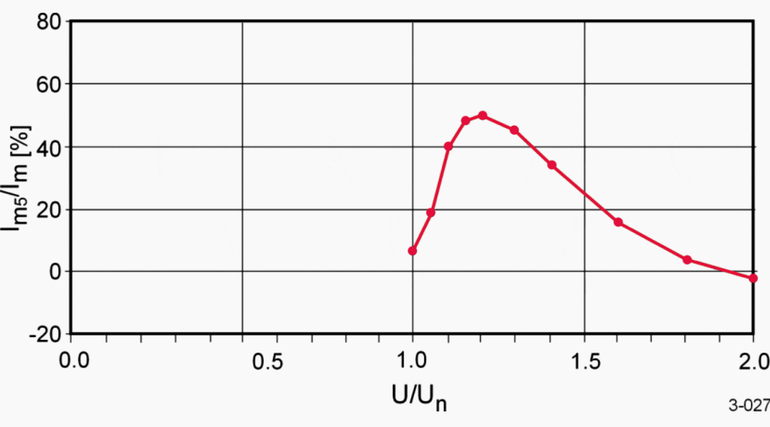

The phenomenon related to an increasing magnetizing current as a result of increasing supply voltage is referred to as over-excitation.
3. Secondary Voltage Adjustment
The voltage level supplied to the load from the transformer secondary terminals should be kept within certain limits. Factors affecting the fluctuation of the secondary voltage level are the primary side voltage level and the secondary side load current.
To enable the secondary voltage adjustment to compensate these fluctuations, the voltage transformation ratio of the power transformer has to be adjustable.
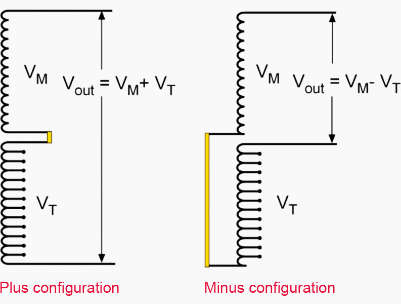
This adjustment is made possible by introducing a number of tappings in the windings. These tappings are usually placed in the primary side windings to minimize the current passing through the switch providing connection to the different taps.
The tap changer’s physical placement with power transformer can be inside the main tank (intank type), in other words within the same oil-filled enclosure where the windings are.
The other possibility is to have the tap changer outside the main tank (on-tank or container type) within its own oil-filled enclosure attached to the side of the main tank.
Three different tapping switch implementation principles can be identified, namely:
- Plus-minus switching,
- Linear switching and
- Coarse-fine switching.
Out of these three, the first one, plus-minus switching, is the most common. The operation principle is shown below.

Typically, the on-load tap changer is motor-operated, providing a possibility for remote control. The off-load tap changer is most commonly having manual operation facilities only, but also a motor operation is possible.
The operation of an on-load tap changer can be automated using an automatic voltage regulator (AVR), as is explained here.
How On Load Tap Changer Works (VIDEO)
This video explains how an On Load Tap Changer (OLTC) works. On Load Tap Changers are used in liquid immersed electrical transformers in the power engineering industry. The purpose of the tap changer is to regulate the number of secondary windings within the circuit.
By changing the amount of conductor (windings) within the changing magnetic field, the induced voltage output can be regulated.
How Off Load Tap Changer Works (VIDEO)
This 3D animated video explains how an off load tap changer works. Off load tap changers are fitted to electrical transformers and are sometimes referred to as de-energized tap changers, or no load tap changers.
4. Transformer connection groups
The power transformer connection groups are indicated with letter and number symbols. Capital letters refer to the winding having the highest rated voltage and small letters to winding(s) having a lower rated voltage.
- Y and y: are referring to a star-connected winding.
- D and d: are referring to a delta-connected winding
- Z and z: are referring to a zigzag-connected winding
- III and iii: are referring to an open (not connected) three-phase winding.
- N and n: indicate that the neutral terminal of a star-connected winding is brought to the surface.
- a: indicates an auto-type of winding connection.
The numbers used are from 1 to 12(0) referring to a normal clock’s time dial.


Three-phase transformers are usually operated with the high-voltage and low-voltage windings connected in:
- Y (star),
- D (delta) or
- Z (zigzag) connection.
The three styles are shown in Figure 6.


In star connection, one end of each of the three-phase windings is joined together at a neutral point N and line voltage is applied at the other end; this is shown in Figure 6(a).
The advantages of star connection are:
- It is cheaper for a high-voltage winding.
- The neutral point is available.
- Earthing is possible, either directly or through an impedance.
- Reduced insulation level (graded insulation) is possible at the neutral.
- Winding tappings and tap-changer may be located at the neutral end of each phase, with low voltages to earth and between phases.
- Single-phase loading is possible, with a neutral current flowing.
In delta connection, the ends of the three windings are connected across adjacent phases of the supply as shown in Figure 6(b).
The advantages of a delta connection are:
- It is cheaper for a high-current low-voltage winding
- In combination with a star winding, it reduces the zero-sequence impedance of that winding
The zigzag connection is used for special purposes where two windings are available on each leg and are interconnected between phases as shown in Figure 6(c).
The main advantage of a zigzag connection is: It permits neutral current loading with an inherently low zero-sequence impedance, and it is used in grounding transformers to create an artificial neutral terminal on the system
Transformer vector group (VIDEO)
This video outlines the vector groups that you will come across on a typical transformer and explains the principles of phase shift.
5. Short Circuit Impedance
The following discussion is introducing the (sequence) impedances in relation to three-phase power transformers.
For three-phase transformers, the impedance is expressed as phase impedance. This quantity is often expressed in relative, dimensionless form, as a fraction zpu of the reference impedance Zref [Ω/phase].


Or in percentage notation:


The reference impedance Zref [Ω/phase] can be calculated from the reference voltage Uref [V], reference current Iref [A] and reference apparent power Sref [VA] as follows.
![Reference impedance Zref [Ω/phase]](https://electrical-engineering-portal.com/wp-content/uploads/2019/01/reference-impedance-formulae.gif)
![Reference impedance Zref [Ω/phase]](https://electrical-engineering-portal.com/wp-content/uploads/2019/01/reference-impedance-formulae.gif)
Combining the above formulas results in:


And starting from percentage values:


The real part of the impedance can be calculated based on the rated load losses PL [W]. The following formula gives the result in percent r% [%].
![Percent r [%] formulae](https://electrical-engineering-portal.com/wp-content/uploads/2019/01/percent-r-formulae.gif)
![Percent r [%] formulae](https://electrical-engineering-portal.com/wp-content/uploads/2019/01/percent-r-formulae.gif)
The imaginary part x% [%] can be calculated as follows:


The real R [Ω/phase] and imaginary part X [Ω/phase] of Z [Ω/phase] can be calculated as follows:
![Real R [Ω/phase] and imaginary part X [Ω/phase] of Z [Ω/phase]](https://electrical-engineering-portal.com/wp-content/uploads/2019/01/real-imaginary-part-formulae.gif)
![Real R [Ω/phase] and imaginary part X [Ω/phase] of Z [Ω/phase]](https://electrical-engineering-portal.com/wp-content/uploads/2019/01/real-imaginary-part-formulae.gif)
6. Transformer Sequence Impedances
Here are introduced the sequence impedances related to power transformers. The following definitions are used:
- Z1 is the positive-sequence impedance [Ω/phase]
- Z2 is the negative-sequence impedance [Ω/phase]
- Z0 is the zero-sequence impedance [Ω/phase]


The following equation below can be used to calculate the zero-sequence impedance Z0 [Ω/phase] using voltage U [V] and current I [A] as defined in Figure 7 above.
![Zero-sequence impedance Z0 [Ω/phase]](https://electrical-engineering-portal.com/wp-content/uploads/2019/01/zero-sequence-impedance-formulae.gif)
![Zero-sequence impedance Z0 [Ω/phase]](https://electrical-engineering-portal.com/wp-content/uploads/2019/01/zero-sequence-impedance-formulae.gif)
With transformers:
![]()
![]()
The positive- and negative-sequence impedances equal the short circuit impedance, whereas the zero-sequence impedance differs considerably.
The factors affecting the zero-sequence impedance are:
- Transformer connection group
- Core- or shell-type construction
- 3- or 5-limb or three-phase bank constructed of single-phase units
Furthermore, the stated values refer to a core-type construction with three-limb design.
The following definitions have been used:
- H: High-voltage (primary) winding
- L: Low-voltage (secondary) winding
- T: Tertiary winding
- E: Earth potential
- z: Relative short circuit impedance
- z0HL: Relative zero-sequence impedance from high-voltage to low-voltage side
- z0HE: Relative zero-sequence impedance from high-voltage side to earth
- z0LE: Relative zero-sequence impedance from low-voltage side to earth


If the above presented power transformer is of the five-limb design or the three-phase bank is constructed out of single-phase units, the values of Z0HE and Z0LE are basically infinite.


If the above presented power transformer is of the five-limb design or the three-phase bank is constructed out of single single-phase units, the z0HE in the YNd-connection is equal to z.


Normal procedure for the power transformer manufactures is to state the zero-sequence impedance in relative values, either as a fraction or a percentage of the reference impedance.
For calculating the actual ohmic values, the same equations as introduced for the short circuit impedance calculations can be used.
For three-winding power transformers, the calculation of zero-sequence impedance ohmic values is a bit more complicated.
In this example, the following information is available in the power transformer’s data sheets.
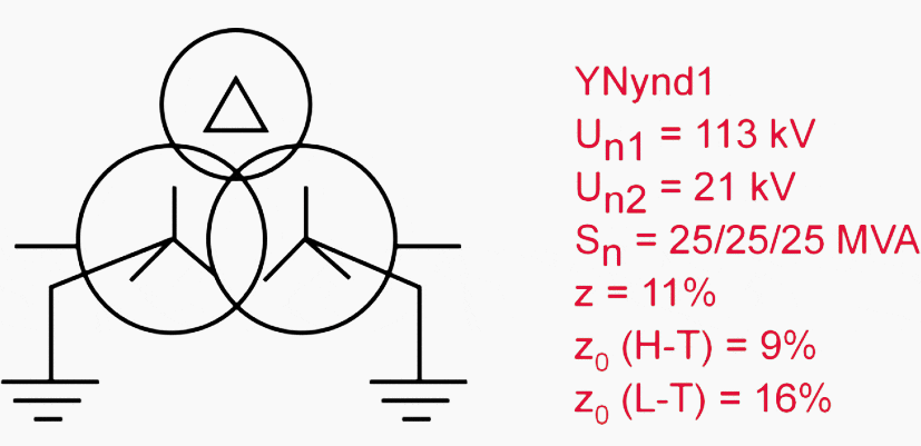

The following figure shows the zero-sequence impedance components whose ohmic values should be calculated based on the above data.
It is assumed here that the impedances are pure reactance, and the chosen reference voltage is 21 kV (low-voltage side of the transformer).
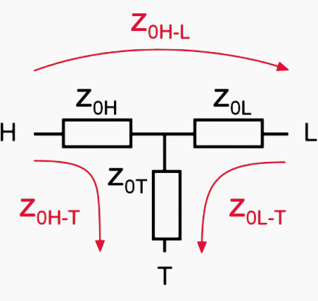

Calculation of the ohmic values based on the transformer’s given data:
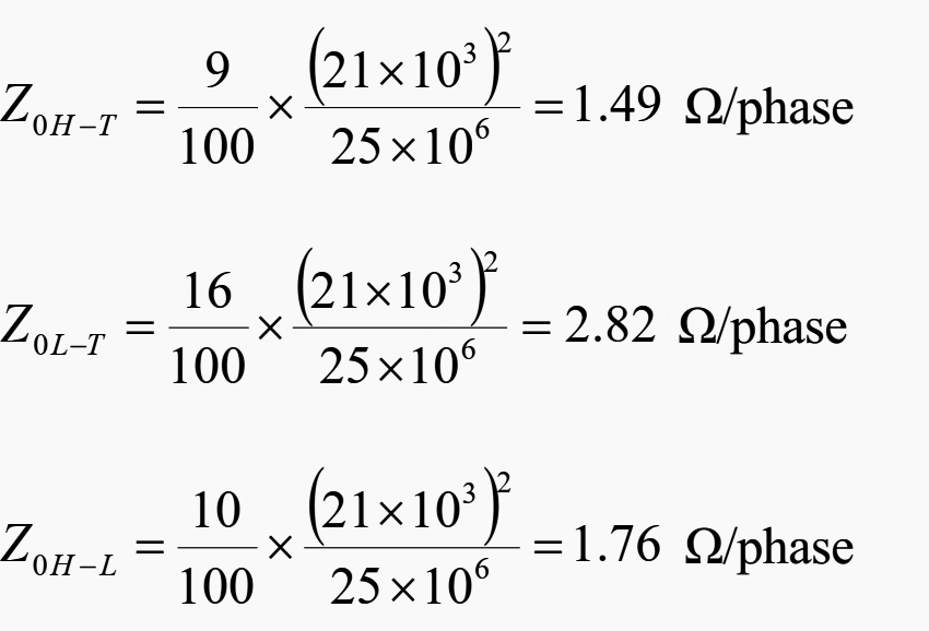

The specific component impedances are then calculated.
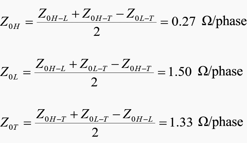

Sequence Impedances of Transformer
Sources:
- Elements of power distribution systems by ABB
- Electrical installation guide by Schneider Electric
- Power Engineer’s Handbook by D.F. Warne



It’s nice to learn more through your experience
Dear sir
Thanks for your attention and efforts, we are a composite insulator producer here in Iran and have a problem with our clients and their consulting engineers, they request some figures for silicone rubber compound data sheet which compound manufacturers does not accept, for example, any of manufacture do not write silicone amount in their datasheet even when we ask them to make silicone rubber compound containing 50% silicone by weight, and higher dielectric strength and tear strength they don’t accept as well,in the other hand there is not any standard to submit optimum amount of silicone and fillers and additives in silicone rubber for high voltage insulators,would you please talk about this with your colleagues to give a reasonable datasheet for silicone rubber specification containing formulation and composition.
Your kind attention and a prompt reply are appreciated.
Best regards: Reza Tousipanah
Section 1 (Inrush Current): The embedded youtube video illustrates the inrush current where the transformer secondary is open-circuit when the primary is energized, but it doesn’t deal with the case where the secondary will be supplying full load from the instant of transformer switch-on. Maybe an additional video is available from the same youtube commentator (or if not, some appropriate wording could be added just after that point).