
Estimated Study Time: 5 minutes
Turns ratio between the windings
Power transformer turns ratio test is an AC low voltage test which determines the ratio of the high voltage winding to all other windings at no-load. The turns ratio test is performed on all taps of every winding.

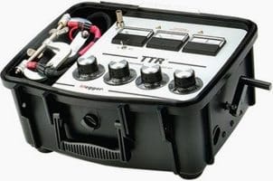
The Transformer Turns Ratio tester (TTR) is device used to measure the turns ratio between the windings (example shown below).
Voltage is applied on the H marked leads and measured of the X marked lead by the test set.
Ratio measurements are conducted on all tap positions and calculated by dividing the induced voltage reading into the applied voltage value. When ratio tests are being made on three-phase transformers, the ratio is taken on one phase at a time with a three-phase TTR until the ratio measurements of all three phases are completed.
Measured ratio variations should be within 0.5% of the nameplate markings.
Some TTR can perform transformer ratio measurement and also assess if on-load tap changer contacts are making satisfactorily during its transition from one tap position to the next position.
Turns Ratio Test Procedure, Step by Step
Step 1.
Isolate the equipment, apply working grounds to all incoming and outgoing cables and disconnect all incoming and outgoing cables from the transformer bushing terminals connections.
Disconnected cables should have sufficient clearance from the switchgear terminals greater that the phase spacing distance. Use nylon rope to hold cable away from incoming and outgoing terminals as required.
Step 2.
Connect the H designated three-phase test lead with the military style connector at one end to the mating connection on the test set marked with an H. Ensure that the connector’s index notch lines up properly.
Step 3.
Connect the X designated three-phase test of lead military style connector at one end to the mating connection on the test set marked with an X. Ensure that the connector’s index notch lines up properly.
Step 4.
Connect the H1, H2, H3 designated test lead to the corresponding H1, H2, H3 transformer terminal / bushing. Connect the H0 test lead if H0 terminal/bushing is present.
Refer to Figure 1.
Step 5.
Connect the X1, X2, X3 designated test leads to the corresponding X1, X2,X3 transformer terminals / bushings. Connect the X0 test lead if X0 terminal/bushing is present.
Step 6.
Perform turns ratio measurements for all tap positions.
Step 7.
Confirm that the measured ratios is within 0.5% of the calculated ratios.
Important Note:
Transformers that have wye connections but do not have the neutral of the wye brought out shall be tested for ratio with three-phase power supply.
Any inequality in the magnetizing characteristics of the three phases will then result in a shift of the neutral and thereby cause unequal phase voltages. When such inequality is found, the connection should be changed, either to a delta or to a wye connection, and the line voltages measured.
When these are found to be equal to each other and the proper values (1.732 times the phase voltages when connected in wye), the ratio is correct.
Power Transformer Testing
Automatically measuring ratio and winding resistance of all taps/phases.
Reference: Substation Commissioning Course – Raymond Lee, Technical Trainer
Related electrical guides & articles


Edvard Csanyi
Hi, I'm an electrical engineer, programmer and founder of EEP - Electrical Engineering Portal. I worked twelve years at Schneider Electric in the position of technical support for low- and medium-voltage projects and the design of busbar trunking systems.I'm highly specialized in the design of LV/MV switchgear and low-voltage, high-power busbar trunking (<6300A) in substations, commercial buildings and industry facilities. I'm also a professional in AutoCAD programming.
Profile: Edvard Csanyi

Can I TTR a 115kv to 27kv transformer before it has been filled with oil?
I was contacted by out testing crew and they mentioned that when conducting TTR the values read are all 2 taps behind for indication on all tap positions i.e. when measuring tap 7 the ratio obtained is that of tap 5. The transformer is a YnD1 with an automatic tap changer. What could be the problem?
How can I test for transformer ratio, excitation, characteristics and insulation?
Engineering is a marvelous self liable course.
Thank u sir for your brilliant explanation, apart from TTR meter which methods can I use to carry ratio test using multi meter.pls also attached diagrams .
Sir please,i need to learn more about ratio test and capacity testing. I get confused sometimes place hope me out. Thanks
Thanks for your brilliant explanations sir. please sir i need your help, i work with a transformer manufacturing industry here in Nigeria. i have been taxed to carryout an r&d on transformer insulation degradation using partial discharge effect on the insulation. please i need your assistance in this.
Thanks
Kind Regards
Tom-Davies
this site is really very educating keep it up
Thanks for educating session on this all important portal. I really fascinated by your in-dept analysis.
Salaam to all..
Can any one clear plz that if there is difference b/w the nameplate value and tested value of TTR then what fault should b in Transformer??
I am electrical technician in a workshop deals with transformer repairing and overhauling. i need to learn transformer testing techniques through your discussions which are very fruitfull
Very nice. Thank you
difference between line turn ratio and phase turn ratio of 3-phase transformer.
Request for how to perform timing test and contact resistance test
You must be using portable transformer turns ratio (TTR) meter. I am used to applying 3-phase 415 V generator to the HV side and then measuring the induced V on the LV…. Can you explain the second method and possibly post the equipment setup diagram? I do have it but you know…Hahahaha…
Could you pls clarify the following..
What will be the voltage ratio or turns ratio
Yzn11, 100 kVA, 20000/400 V zigzag transformer
NICE
Hai sir .
I need to know about the load cells
Standard is IEC 60076
Please, Could You tell me what standard describes this test?
Nice