
Estimated Study Time: 29 minutes
Commissioning of Power Transformers
Since I started the commissioning work 30 years back, transformer commissioning consisted of more tests, but nowadays, the number of tests has been reduced due to costs and time-saving. This article will go through complete testing that needs to be done at the site during the commissioning process of the transformer.
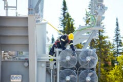
 Power transformers testing and commissioning at the site (on photo: Transformer dynamic resistance measurements with the Omicron's CPC 100)
Power transformers testing and commissioning at the site.
- Power transformer tests:
- Measurement of Winding Insulation Resistance
- Winding Resistance Test
- Voltage Ratio Test
- Polarity Test
- No-Load Losses Test
- Load Losses (Short Circuit) Test
- Vector Group Test
- Capacitance and tan δ Test
- Oil Breakdown Test
- Temperature Rise Test
- Frequency Response Analysis (FRA Test)
- Partial Discharge Test
- Transformer General Tests
- Transformer Primary Tests
- Transformer Secondary Tests
- Transformer Tripping Tests
- Transformer Load Tests
1. Power Transformer Tests
These tests include winding insulation resistance test, winding resistance test, vector group test, tan delta test, no-load test or iron losses, load test or copper losses, temperature rise test, partial discharge test, frequency response analysis test, and transformer oil breakdown test.
These tests are detailed as follows:
1.1 Measurement of Winding Insulation Resistance
The purpose of this test is to determine the insulation resistance of the high-voltage winding to the ground, low-voltage winding to the ground, and the high-voltage winding to the low voltage winding, also to assess the amount of moisture in transformer insulation.
This test should be done between the windings as follows:
- High Voltage winding to the Earth as shown in the figure given below.
- Low Voltage winding to the Earth same as HV-Earth but the connection will be between LV-Earth.
- The high voltage winding to the low Voltage Windings as shown in the figure given below.
Figure 1 – Insulation resistance testing: HV-Earth and HV-LV
We take the reading after 15 sec and after 60 sec the result will give the polarization index of transformer insulation, which indicates the transformer insulation condition.
Polarization Index (PI) =R60/R15 should be as follows:
- More than 1.3 for the transformer with voltage up to 35kV
- Between 1.5 to 1.7 for transformers with voltage range from 66 kV up to 500 kV
- If PI reading is more than 3.1 this means the transformer insulation is in good condition.
- As a guide for practical reading:
- LV-Earth 1 G-Ohm.
- HV-Earth 2.5 G-Ohm.
- L.V to H.V 2.5 G-Ohm.
Conclusion:
Do not choose the megger test voltage as standard 5000 volts as some transformer’s manufacture has low insulation for big transformer neutral points, for example, 500MVA, 500kV Transformers and if you apply 5000 D.C voltage in the winding you will lose the transformer windings, so please refer to the specified D.C voltage to test the transformer windings as per manufacture manual instruction.
If you find the insulation resistance is not satisfied, further investigation should be done in the transformer before energization.
For Megger, discharge the current to avoid shock. Switch off the power supply when connecting the circuit to avoid a spark.
Go back to the Contents Table ↑
1.2 Winding Resistance Test
The purpose of this test is to measure the D.C. resistance of the transformer windings, this test can be done by a voltmeter and ammeter method. For low reading values, we connect the voltmeter after the ammeter, but for high resistance values, we connect the voltmeter before the ammeter. A sensitive voltmeter and ammeter will be used with a 100 DC Amp. This test will give accurate results as shown below:
Figure 2 – DC winding resistance test (current-voltage method)

This test can be done when a transformer is hot or cold, but the temperature of the winding and oil should be recorded during the test. If a transformer for example delta/star windings, then check the resistance as follows:
- HV winding resistance between phase R and phase S
- HV winding resistance between phase S and phase T
- HV winding resistance between phase T and phase R
- LV winding resistance between phase R and neutral N at Tap 9
- LV winding resistance between phase S and neutral N at Tap 9
- LV winding resistance between phase T and neutral N at Tap 9
As a practical guide for a power transformer 66/33 kV, 20 MVA we have the following values measured at the site:
H.V Side, Tap Changer on Tap Number 9:
- The resistance between windings R and winding S is 824 mOhm
- The resistance between windings S and winding T is 832 mOhm
- The resistance between windings T and winding R is 763 mOhm
L.V Side, Tap Changer on Tap Number 9:
- The resistance between windings R and neutral N is 78 mOhm
- The resistance between windings R and neutral N is 79 mOhm
- The resistance between windings R and neutral N is 79.5 mOhm
Conclusion:
If the values of the winding resistance are low do not energize the transformer there a possibility of winding damage.
VIDEO: – Measuring DC winding resistance and checking the tap changer
Go back to the Contents Table ↑
1.3 Transformer Voltage Ratio Test
The simple method is to inject 380 Volts at the site on high-voltage winding and to take the readings of the injected on a high-voltage and low-voltage at each tap. This can also be done by a small portable transformer with a fixed primary winding and a secondary with large numbers of taps connected to selector switches for coarse and fine adjustment of the reading or an autotransformer.
After injecting a voltage of 220 volts on the HV side of the transformer under test (connected to the primary winding of the ratio meter), the voltage induced in the voltage winding of the power transformer will be compared to the secondary voltage of the ratio meter.
Also, this test can be done more easily by using modern devices to measure the ratio by different manufacturers such as Megger and Omicron CPC100, etc. as shown below. The error should be within ± 5% of the transformer nameplate ratio.
VIDEO: – Explaining transformer turns ratio test
VIDEO: – How to perform a transformer turns ratio test
VIDEO: – Measuring ratio and winding resistance of all taps/phases
Conclusion:
- Do not do this test if the transformer is under a vacuum process or there is any doubt for any short circuit in transformer windings, this vacuum can cause flashover or fire, or explosion.
- If the error exceeds ± 2% from nameplate values, different causes should be investigated to rectify.
- Wrong connections in tap changer.
- Short circuit in transformer windings.
- By the end of the test earth the transformer windings to discharge it.
Go back to the Contents Table ↑
1.4 Transformer Polarity Test
The purpose of this test is to identify the beginning and end of the primary winding to the beginning and end of the secondary windings of the power transformer. Defining polarity is important to identify the direction of the induced voltage in the transformer winding.
Polarity can be tested using the AC or the DC circuit as shown below.
Figure 3 – Transformer polarity test scheme
In the A.C circuit test method shown above in Figure 3(a), we use an AC voltage source and three voltmeters. If the reading of V3 is the sum of V1-V2, then we have the correct polarity shown in the circuit. In the DC circuit test method, we use a suitable battery, switch, and a sensitive moving-coil galvanometer. Closing the switch instantaneously causes the moving of the pointer in the galvanometer, and if it is in the positive direction then the polarity is ok.
In the new testing devices from different manufacturers, there is a feature to detect the correct polarity of the transformer automatically.
Related electrical guides & articles


Omar Salah
I have an Engineering Msc/Bsc Degree and more than 25 years of experience in commissioning activities, mainly at thermal power plant gas/oil-fired, combined cycle and petroleum power plants, and 11kV - 500kV substations. I worked with many international companies as an electrical commissioning manager and as an expert in setting protection relays in many different projects in Egypt.Profile: Omar Salah
