
Estimated Study Time: 13 minutes
Private substations
Private substations can often be considered as terminal type substations, i.e. substations where the MV line ends at the point of installation of the substation itself. They belong to the user and can supply both civil users (schools, hospitals, etc.) with power and industrial users with supply from the public MV grid.
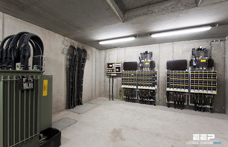 Practical Considerations of LV/MV Private Substations (on photo: MV/LV secondary substation; credit: bauschdatacom.com)
These private substations are mostly located in the same rooms of the factory they supply.
It is normally expected that the customer use MV/LV transformers with //
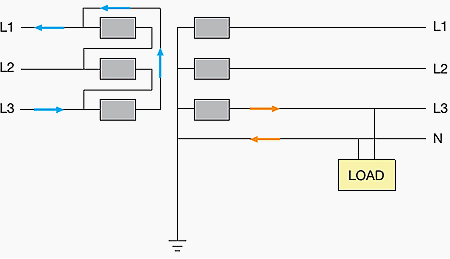
Delta primary winding (Δ)
Because, thanks to this connection type, the third harmonics of the magnetizing currents (distorted due to the non-linearity of the magnetic circuit) and any possible homopolar current are free to circulate through the sides of the delta, without flowing into the network. Thus, the magnetic fluxes remain sinusoidal and consequently also the fem induced at the secondary.
Besides, in case of unbalanced loads at the secondary winding, the reaction current absorbed by the primary flows only through the corresponding winding (as shown in the figure) without affecting the other two. If this should occur, as in the star connection, the currents in those windings would be magnetizing currents and would cause an asymmetry in the phase voltages.
Only when special applications are provided (welding machines, actuators, etc.), the connection can be not of delta type and the choice shall be agreed on with the utility.
Secondary winding with grounded star point
To make line and phase voltages easily available, but above all for safety reasons, since, in the event of a fault between the MV and LV sides, the voltage at the secondary remains close to the phase value, thus guaranteeing higher safety for people and maintaining the insulation.
These prescriptions specifically apply to connections to the MV grid with rated voltage of 5kV and 20kV whereas, for other MV voltage values, they can be applied for similarity.
As an example, below we give the prescriptions provided by an Italian distribution utility regarding the power of the transformer which can be used.
The power values allowed are as follows //
- Power not higher than 600kVA for 5kV networks
- Power not higher than 2000kVA for 20kV networks
The powers indicated refer to a transformer wit vk%=6%. The limit relative to the installable power is also established and, in order not to cause unwanted trips of the overcurrent protection of the MV line during the putting into service operations of their own plants, the customers cannot install more than three transformers, each of them with size corresponding to the limits previously indicated and with separated LV busbars.
Moreover, the users cannot install transformers in parallel (voltage busbars connected) for a total power exceeding the mentioned limits so that, in case of a LV short circuit on the supply side of the LV main circuit breaker, only the MV circuit breaker of the user, installed to protect the transformer, and not the line protection device of the utility, trips.
In those cases when the customer’s plant is not compatible with the aforesaid limitations, it will be necessary to take into consideration other solutions, for example providing power supply through a dedicated line and customizing the settings of the overcurrent protective device.
The transformer is connected to the take-up point in the delivery room by means of a copper connection cable which, regardless of the power supplied, must have a minimum cross-section of 95 mm2. This cable is the property of the user and must be as short as possible.
The present trend regarding management of the earthing connection of the system is to provide the passage from insulated neutral to earthed neutral by means of impedance.
This modification, needed to reduce the singlephase earth fault currents which are continually on the increase due to the effect of growingly common use of underground or overhead cables, also implies upgrading the protections against earth faults both by the utility and by the customers.
Private substations supplied by a single MV line
The intention is to limit unwanted trips as far as possible, thereby improving service. After having indicated what the main electrical regulations for a MV/LV substation are, let’s now analyse what the most common management methods may be in relation to the layout of the power supply transformers for a private substations supplied by a single medium voltage line.
- Substation with a single transformer
- Substation with two transformers with one as a spare for the other
- Substation with two transformers which operate in parallel on the same busbar
- Substation with two transformers which operate simultaneously on two separate half-busbars
Method #1
Substation with a single transformer
When the plant foresees installation of an “IMV” overcurrent protection device where the line which supplies the substation originates, as shown in single line diagram, this device must ensure protection of both the MV line as well as the transformer.
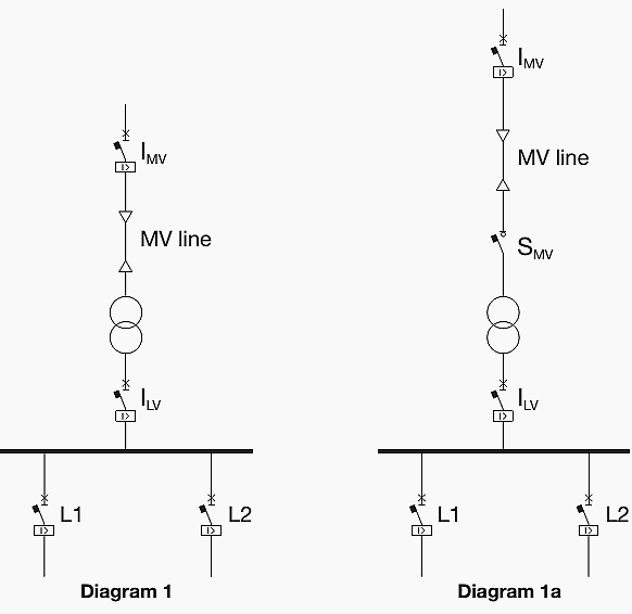
In the case where the protection device also carries out switching and isolation functions, an interlock must be provided which allows access to the transformer only when the power supply line of the substation has been isolated.
Another management method is shown in Single line diagram 1a, which foresees installation of the “SMV” switching and isolation device positioned immediately to the supply side of the transformer and separate from the protection device which remains installed at the beginning of the line.
Go back to Private Substations SLDs ↑
Method #2
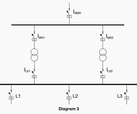
Substation with two transformers with one as a spare for the other
When the plant foresees installation of a transformer considered as a spare, the circuit breakers on the LV side must be connected with an “I” interlock whose function is to prevent the transformers from operating in parallel.
Apart from the switching and isolation device on the incoming MV line (IGMV), it is advisable to provide a switching, isolation and protection device on the individual MV risers of the two transformers (IMV and IMV2) as well.

In this way, with opening of the device on the supply and load side of a transformer, it is possible to guarantee isolation and access the machine without putting the whole substation out of service.
Go back to Private Substations SLDs ↑
Method #3
Substation with two transformers which operate in parallel on the same busbar
When the plant foresees installation of two transformers operating in parallel at the same overall power required of the plant, it is possible to use two transformers with lower rated power.
Compared with the management method described in the two previous cases, higher short circuit currents could be generated for faults in the low voltage system due to reduction of the possible vk% for lower power machines.
Operation in parallel of the transformers could cause greater problems in management of the network. Again in this case, however, outage of a machine might require a certain flexibility in load management, ensuring the power supply of those considered to be priority loads.
When coordinating the protections, the fact that the overcurrent on the LV side is divided between the two transformers must be taken into consideration.
Go back to Private Substations SLDs ↑
Method #4
Substation with two transformers which operate simultaneously on two separate half-busbars
Starting from the previous management method, by providing a “CLV” bus-tie and an “I” interlock which prevents the bus-tie from being closed when both the incoming circuit breakers from the transformer are closed, a substation managed as shown in single line diagram 4 is made, which foresees two transformers which individually supply the low voltage busbars, which are separate.
In other words, each transformer establishes the short circuit level for the busbar of its competence without having to consider the contribution of other machines.
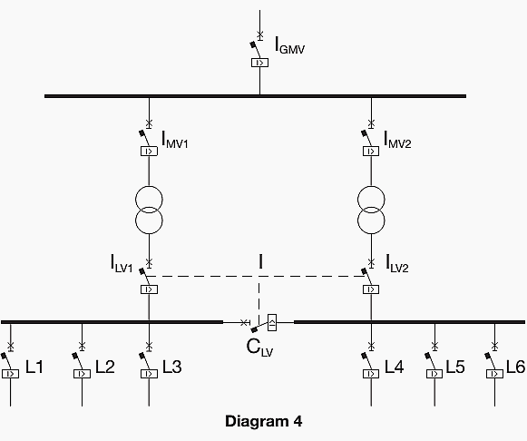
Again in this case, when a transformer is out of service, with any closure of the bus-tie you pass to a system with a single busbar supplied by the sound transformer alone, and a load management logic must be provided with disconnection of non-priority loads.
Plant management according to single line diagram 4 is possible, for example by using the ABB’s ‘Emax’ series of air circuit breakers with a wire interlock (mechanical interlock) between three circuit breakers.
Go back to Private Substations SLDs ↑
Reference // MV/LV transformer substations: theory and examples of short circuit calculation – ABB
Related electrical guides & articles


Edvard Csanyi
Hi, I'm an electrical engineer, programmer and founder of EEP - Electrical Engineering Portal. I worked twelve years at Schneider Electric in the position of technical support for low- and medium-voltage projects and the design of busbar trunking systems.I'm highly specialized in the design of LV/MV switchgear and low-voltage, high-power busbar trunking (<6300A) in substations, commercial buildings and industry facilities. I'm also a professional in AutoCAD programming.
Profile: Edvard Csanyi

Iam interested in electrical protection system.
Hello , I am really interested in learning lots of information from you . I am electrical engineer and wanna be professional engineer for my future carier . Can you help me ? Thanks before
Can one have professional training certificate from you?
How can we get professional training from you?
Hello , I am really interested in learning lots of information from you . I am electrical engineer and wanna be professional engineer for my future carier . Can you help me ? Thanks before
Pls do you organise trainings?
Hi
Am interested with the electrical protection system
I want full detail lv control panel design with using a protection and safety plant and also known about distributed a supply in plant.
How can one get professional training from you ?
Really appreciate ur article & professionalism
I have a question.
What happens if each separate half-busbar is in a different room.