
Inrush current phenomenon
When a transformer is initially connected to a source of AC voltage, there may be a substantial surge of current through the primary winding called inrush current. This is analogous to the inrush current exhibited by an electric motor that is started up by sudden connection to a power source, although transformer inrush is caused by a different phenomenon.
 Practical Considerations Of Transformer Inrush Current (photo credit: winderpower.co.uk)
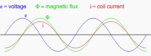
In a continuously-operating transformer, these two waveforms are phase-shifted by 90º (see Figure 1 below).
Since flux (Φ) is proportional to the magnetomotive force (mmf) in the core, and the mmf is proportional to winding current, the current waveform will be in-phase with the flux waveform, and both will be lagging the voltage waveform by 90º:
Let us suppose that the primary winding of a transformer is suddenly connected to an AC voltage source at the exact moment in time when the instantaneous voltage is at its positive peak value. In order for the transformer to create an opposing voltage drop to balance against this applied source voltage, a magnetic flux of rapidly increasing value must be generated.
The result is that winding current increases rapidly, but actually no more rapidly than under normal conditions (see Figure 2). Both core flux and coil current start from zero and build up to the same peak values experienced during continuous operation. Thus, there is no “surge” or “inrush” or current in this scenario. (see Figure 2)

Alternatively, let us consider what happens if the transformer’s connection to the AC voltage source occurs at the exact moment in time when the instantaneous voltage is at zero. During continuous operation (when the transformer has been powered for quite some time), this is the point in time where both flux and winding current are at their negative peaks, experiencing zero rate-of-change (dΦ/dt = 0 and di/dt = 0).
As the voltage builds to its positive peak, the flux and current waveforms build to their maximum positive rates-of-change, and on upward to their positive peaks as the voltage descends to a level of zero:
A significant difference exists, however, between continuous-mode operation and the sudden starting condition assumed in this scenario: during continuous operation, the flux and current levels were at their negative peaks when voltage was at its zero point; in a transformer that has been sitting idle, however, both magnetic flux and winding current should start at zero.
When the magnetic flux increases in response to a rising voltage, it will increase from zero upward, not from a previously negative (magnetized) condition as we would normallyhave in a transformer that’s been powered for awhile.
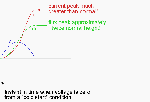
Thus, in a transformer that’s just “starting,” the flux will reach approximately twice its normal peak magnitude as it “integrates” the area under the voltage waveform’s first half-cycle: (Figure 4)


In an ideal transformer, the magnetizing current would rise to approximately twice its normal peak value as well, generating the necessary mmf to create this higher-than-normal flux.
During saturation, disproportionate amounts of mmf are needed to generate magnetic flux. This means that winding current, which creates the mmf to cause flux in the core, will disproportionately rise to a value easily exceeding twice its normal peak (Figure 5).
This is the mechanism causing inrush current in a transformer’s primary winding when connected to an AC voltage source. As you can see, the magnitude of the inrush current strongly depends on the exact time that electrical connection to the source is made.
If the transformer happens to have some residual magnetism in its core at the moment of connection to the source, the inrush could be even more severe. Because of this, transformer overcurrent protection devices are usually of the “slow-acting” variety, so as to tolerate current surges such as this without opening the circuit.
Reference // Lessons In AC Electrical Circuits – Tony R. Kuphaldt


Dear Edvard, I have a very special application that needs to lower the voltage and then, after going through an automatic voltage controller, the voltage needs to be raised again.
In other words, we would have 3 transformers in series of 2 MVA each. I understand that a small power outage could cause a very high inrush current. The question is what is that current value. When the power transformers are in parallel I have no doubt, the question is when 3 transformers are connected in series. Are the inrush currents in each of them simultaneous or out of phase in time? Thanks in advance!
I was wondering if transformer inrush current is an overcurrent or earth fault this is because I have seen while energizing transformer sometime the relay pick it up as overcurrent and sometimes the relay pick it up as earth faulty.
Easy, practcal, informative and usefull article to understand the Inrush Current phenomenon in transformes.
Thanks a lot Mr. Edvard Csanyi for sharing this valuable information
Very informative, this article fully explains
why inrush current occurs
so how does this current returns to normal values. How does the inrush dies out after a few cycles.
The transformer is tripping on inrush as I understand and not on RCD.
RCD will only operate with current flow to earth on the primary side in the event of phase to earth fault.
The isolation transformer separates the shore and ships earthing systems for safety and provides galvanic isolation as well to prevent corrosion.
Ship circuits have RCD protection as well for safety.
240V 12kVA is a large isolation supply with nominal current of 50A at 1ph and 63A 1ph supply required. Transformer inrush typically 12 to 15 times FLA of transformer rating and will trip supply CB (Typically Type C circuit breaker) if soft start is not provided with the isolation transformer. Some isolation transformers use pre-magnetising control systems to limit inrush to the FLA of the transformer to avoid tripping of the supply CB.
Regards Patrick
Kudos for every article.These portal is a holy book for electrical engineers.
Edvard-
I thoroughly enjoy your articles!!
I am a marine engineer in the USA. I recently had a case where a private vessel had an 240VAC 12kVA isolation transformer (1:1) installed to isolate ship’s ground from the grid. When plugged into a shore power pedestal with an RCD installed (30mA trip current for a max. of 100mS), the RCD would trip. The transformer manufacture recommended the installation of a soft start module to allow the MMF to develop.
After reading your explanation, I wonder what is really happening that causes the RCD to trip. Instantaneously, 240VAC (L1->L2) is applied across very low resistance primary windings. The RCD senses the differential current between L1 and L2 (N is not brought aboard) and trips if the threshold is exceeded. My confusion comes about because L1 is at one end of the primary winding and L2 is at the other end so I do not understand how the imbalance is generated. Can you or one of your readers enlighten me?
Thanks.
Charlie
good Article…Thanks for sharing