
Estimated Study Time: 30 minutes
Ring Main Units (RMUs)
Ring Main Units are compact modules that are gas-insulated and sealed, comprising main switching devices and ancillary components to ensure continuous secondary power distribution. The precise arrangement and configuration of components always depend on the particular application and loading conditions.
 A Practical Guide to Operation of Ring Main Units
This technical article deals with the RMU operations of medium voltage (11kV to 33kV) underground distribution systems. These systems may be combined within an overhead system or used solely from the zone substation to the distribution transformers.
- Introduction to Ring Main Unit Components:
- Ring Main Unit Configuration
- RMU Operation in Underground and Overhead Systems
- Operation of Switches:
- Remote Terminal Unit
- Voltage Indicators (Neon Indicators)
- SF6 Gas Pressure Indicator
- Earthing of Circuits Connected to Withdrawable Ring Main Units’ Switchgear
- Changing Fuse Switch Fuses
- Practical Course to Ring Main Unit and Medium Voltage Cables in Ring Power Distribution Systems
- Attachment (PDF) 🔗 Download ‘Design Guide for Power Station Auxiliaries and Distribution Systems’
1. Introduction to Ring Main Unit Components
Ring main switchgear is installed in medium voltage underground cable systems throughout the distribution system. Many styles and designs of ring main units are used by Utilities worldwide. They are mainly non-withdrawable units with a few remaining withdrawable units.
All ring main units are made up of one or more of the following:
- Ring main switch, which is a load-break, fault-make switch
- Switch fuse, also called a fuse switch, which is a load-break, fault-make switch equipped with HRC fuses to break fault current
- MV metering tank.
Ring main switch and fuse switch contacts have a ganged three-phase operation. The insulating materials used in the switch contact chamber to extinguish arcing during operation are sulphur-hexafluoride (SF6) in a pressurised sealed chamber, and air (no longer commonly used).
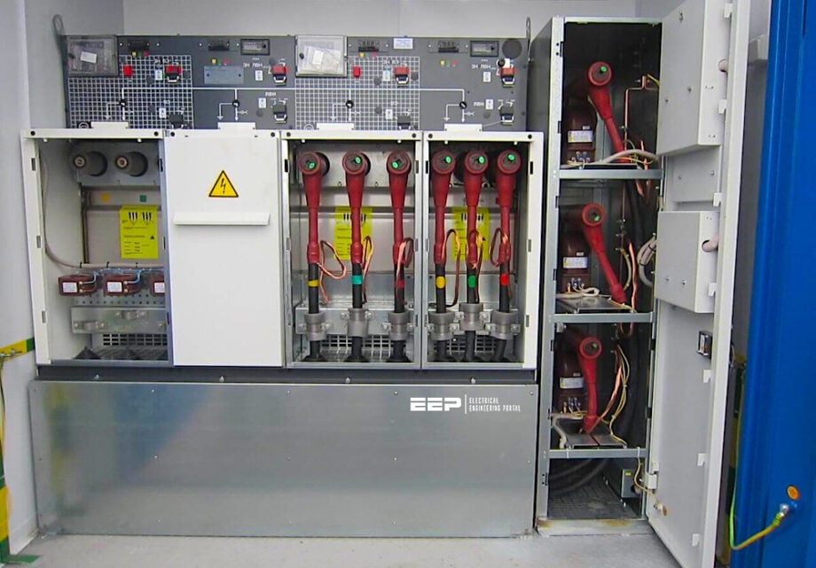
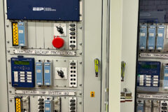
A typical ring main unit is shown Figure 1 below. The ring main unit has a fuse switch in centre position with a switch on either side.
Figure 1 – Typical ring main unit. This RMU is a Schneider RM6 in 2+1 configuration

1.1 Ring Main Switches
These switches are used on distribution underground systems for the same purpose as pole top switches on overhead systems. These three-phase switches are used for interconnection, load movement or isolation of sections of feeder cables.
Ring main switches are connected between the internal bus bar and the cable as shown in Figure 3 and incorporate either an internal earth function or facilities for external earthing. The earth function works on the cable side and not the busbar side of the ring main switch.
Typically, the maximum full load rating of a ring main switch is 630 amps. Particular details for each type of ring main unit can be found on the nameplate.
Watch Video – Main components of Ring Main Unit
1.2 Ring Main Fuse Switches (Fuse Switches)
Fuse switches are used on distribution underground systems for the same purpose as drop out fuses on overhead systems. Switch fuses are used extensively in ring main systems, as an economical means of protecting distribution transformers. They are similar to ring main switches in construction, but include a HV HRC fuse to provide fault interruption and an associated automatic three-phase trip as shown in Figure 3.
The advantages of correctly graded fuses are:
- Quick isolation of the fault, minimising the risks of injury and damage to equipment
- Isolation of only the faulted transformer, keeping maximum supply available to customers.
See Table 1.
Table 1 – Ring main HRC fuse ratings
| Ring Main HRC Fuses | ||||
| Three-phase | kVA | 11kV | 22kV | 33kV |
| 160 | 25 | 10 | 6.3 | |
| 315 | 31.5 | 16 | 16 | |
| 500 | 40 | 25 | – | |
| 630 | 50 | 31.5 | 20 | |
| 750 | 63 | 40 | – | |
| 1000 | 80 | 40 | 40 | |
Important Note! 33kV ground mounted distribution transformers are mainly fed via overhead drop out fuses.
HV HRC fuses consist of a porcelain cylinder with end caps and an internal fuse element and striker pin. The fuses are located in a dry air insulated chamber attached to the switch tank. The components of an HV HRC fuse are shown in Figure 2. Note the yellow arrow on the fuse body, indicating the direction of the striker pin.
Because fuse striker pins are fitted at one end only, the striker pin must be correctly located adjacent to the trip bar mechanism. Note the arrow on the fuse body in Figure 2, indicating the correct direction of the striker pin
Access to a fuse is not possible unless it is isolated, that is, the switch fuse is switched ‘off’.
Figure 2 – Sectional view of a MV HRC fuse

Where switches have an internal earth function, the switch must be put to the ‘earth’ position before access to the fuse chamber is possible. Where switch fuses are withdrawable, they must be switched ‘off’ and racked out for access to the fuses.
Important Note! When changing fuses, the switching operator must remember that the internal bus bar section of the ring main unit is normally energised, and that the fuse must be fitted with the striker pin towards the trip mechanism.
2. Ring Main Unit Configuration
The ring main units consist of the required number of switches and fuse switches to match their application in the network. Figure 3 shows a ring main unit with two switches and two fuse switches. This arrangement is commonly referred to as a 2+2 unit.
Figure 3 – Schneider RM6 two ring main switch and two switch fuse
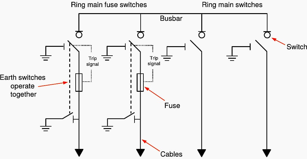
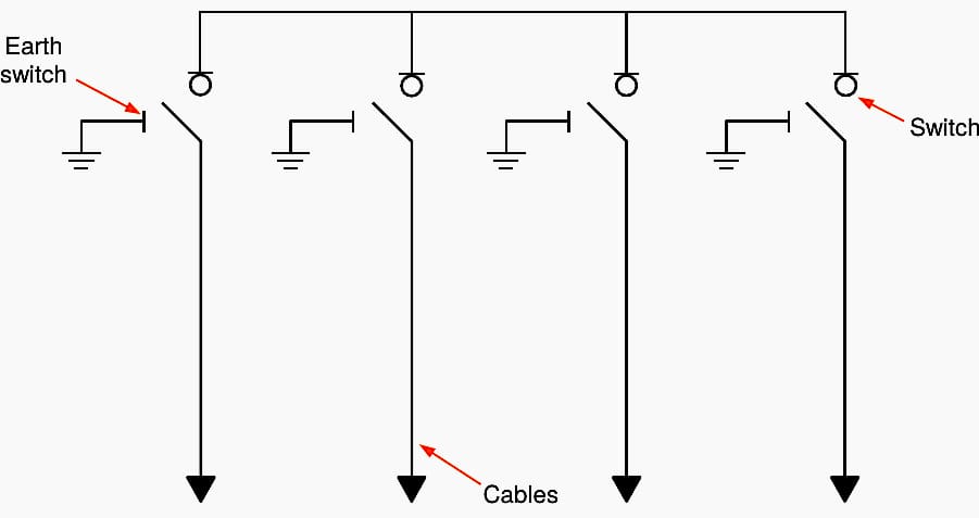
Figure 4 shows a unit with only four switches (4+0 unit).
Figure 4 – Typical Schneider RM6 four ring main switch
Ring main units can be supplied as an extendable or combined (non-extendable) units as shown in Figure 5 and Figure 6. Extendable units provide the capability to build the required configuration by joining together the required number of switch and fuse switch modules. Each module is joined to the next with air-insulated connection joints.
Where the switch and fuse switch modules are SF6 gas-insulated, each module has a separate SF6 chamber and associated pressure gauge.
Combined (non-extendable) units are built by the manufacturer to required configuration inside one tank. Therefore in combined SF6 units there will only be one pressure gauge.
Combined units are commonly used for standard configurations such as 2+1.
Figure 5 – Extendablering main units

Figure 6 – Combined ring main units

Withdrawable and non-withdrawable switches and fuse switches can also be provided. In non-withdrawable units, the switch and fuse switch cannot be withdrawn, disconnecting them from the busbar and cable circuits. Non-withdrawable units are most commonly used.
Figure 7 depicts the principle of withdrawable ring main units with a withdrawable truck unit for both a ring main switch and a switch fuse. The figure shows the truck C may be moved in or out of the housing D. When the ring main switch is inserted into its correct position, it plugs into the HV cable spouts A and the busbar spouts B.
When physically withdrawn the switch separates from the busbar and cable connections as shown for the ring main switch in the right image of Figure 7.
The withdrawable switch fuse is constructed and operated in the same way as a ring main switch but contains three fuses (see Figure 5-9 left). It must be switched ‘off’ and racked out into the withdrawn position out before the fuses can be replaced.
Note the ring main fuse switch on the left is also a withdrawable unit.
Figure 7 – Ring main switch in the service and withdrawn positions

3. RMU Operation in Underground and Overhead Systems
It can be seen that underground and overhead systems are almost identical in operation but there are important differences.
Difference #1 – Ring main units have a cable earthing facility. This may be a switch or manual plug-in device that is used instead of portable overhead earth sets.
Difference #2 – Ring main equipment is designed as full load-break fault-make units. This is not so for pole top switches that have limited capacities.
Difference #3 – Ring main units are designed so that the transformer’s switch fuse opens if a fuse blows.
Difference #4 – The switch contacts are inside the chamber and are not visible. The switching operator must prove the circuit is de-energised before the earths are applied. Some units have neon indicators while others have external testing devices.
Difference #5 – Faults that develop on an underground cable are mostly permanent. Therefore, the substation circuit breaker should not be set to ‘auto reclose’ on circuits that are mainly cable.
Difference #6 – A section of cable may be isolated without loss of supply to a distribution transformer. Usually, this is not possible in the overhead system.
Further Study – Handbook on EHV overhead lines and underground cables
4. Operation of Switches
Ring main switches and fuse switches have three operational positions – ON, OFF and EARTH. A description of the electrical status for each position is shown in Table 2 below.
Table 2 – Operational positions and their electrical status
| Operational Position | Electrical status |
| ON | Busbar is connected to cable |
| OFF | Busbar is disconnected from cable |
| EARTH | The cable is connected to earth |
Most ring main switches and fuse switches have separate switch operating mechanisms or earth switch operating mechanisms, whereby a handle is inserted to operate the switch or earth switch. Switching is restricted to one operation at a time to ensure each operation is separate and deliberate.
Mechanical interlocks between the switch and earth switch mechanisms restrict the allowable combination of the switch and earth switch position to those shown in Table 3 below.
Table 3 – Mechanical interlock status in relation to operational positions
| Operational position | Electrical status | Switch position | Earth switch position |
| ON | Busbar is connected to cable | ON | OFF |
| OFF | Busbar is disconnected from cable | OFF | OFF |
| EARTH | The cable is connected to earth | OFF | ON |
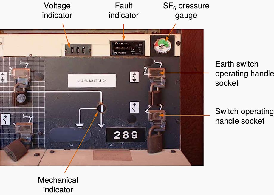
One exception to this arrangement is an old ABB’s ring main unit, which has a plug-in portable earth rather than an earth switch. Figure 8 shows an example of the mechanisms and indicators on the front panel of a ring main unit.
However, this RMU is pretty old (but still in service), and it’s mentioned here as an example of earlier RMU configurations.
Figure 8 – Ring main switch front panel
4.1 Spring-assisted Operation
Ring main switches and earth switches typically have some form of spring assistance in the operating mechanism to ensure the switch contacts move at the rate required to achieve the nominated switching current ratings. As the handle of the switch is operated, it charges a spring that takes over the switching action.
This release of stored energy quickly transfers the switch to the selected position, giving a consistent operation every time.
Earth switches are spring-assisted on closing to ensure rapid earthing of the circuit but in some cases are not assisted on opening.
Watch Video – How to operate RMU
4.2 Drive Motor Spring Charged
Certain types of Schneider switches and breakers make use of a DC drive motor to charge the closing spring. This feature is used when remote switching operations are required on apparatus using a RTU via SCADA. The design of some apparatus does however not include a standard feature to isolate the DC supply to the spring charge motor.
This is a problem when the switch needs to be isolated for the issue of an Electrical Access Permit (EAP).
Operation of the DC isolator must be included in the switching program by the Switching Operator when isolation of the circuit / apparatus is required.
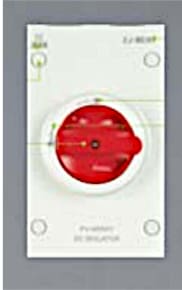
Figure 9 – DC Isolator
5. Remote Terminal Unit (T300)
Remote control functionality of some ring main units via SCADA is achieved by means of a T300 Remote Terminal Unit (RTU). With its flexible approach, Easergy T300 provides optimized solutions for many controlling or monitoring distribution applications.
Typical applications include:
- MV/LV kiosks and chamber substations:
- MV control
- MV automation
- MV current fault detection
- MV & LV broken conductor detection
- LV monitoring
- Volt Var optimization support
- Pole top application Load Break Switch controller:
- Load break switch monitoring and control
- MV current fault detection
- MV broken conductor detection
- Volt Var optimization support
- Pole top and pad mounted transformer monitoring:
- MV and LV broken conductor detection
- Blown fuse detection
- Transformer monitoring
- LV load flow monitoring
- Volt Var optimization support
- LV distribution networks:
- LV broken conductor detection
- Neutral cutout
- Load monitoring
- Theft detection
- Volt Var optimization support
- Distributed Energy Resources grid connection monitoring and control:
- Protection relay connection according to IEC 61850
- Utilities interface
- MV incomer control
- Volt Var optimization support
- MV Line and end of line monitoring:
- MV broken conductor detection
- MV fault detection
- Volt Var optimization support
A single T300 Remote Control Unit is designed to allow remote operation (close, open) of the switches it controls at a particular location. To inhibit remote operation of the RTU and the associated switches it controls, a selection to “local control” must be made on the unit.
Figure 10 T300 Remote Terminal Unit
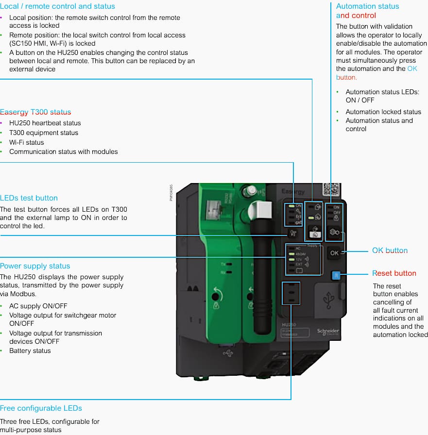
When the unit is selected to “local control”, a LED is illuminated to indicate this.
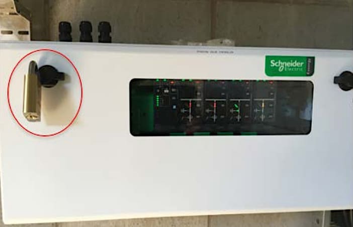
The T300 remote terminal unit is housed in a weather proof lockable enclosure. To prevent the T300 unit from being accessed and inadvertently selected to “remote control” after being selected to “local control”, it must be locked.
Figure 11 – T300 Locked Enclosure
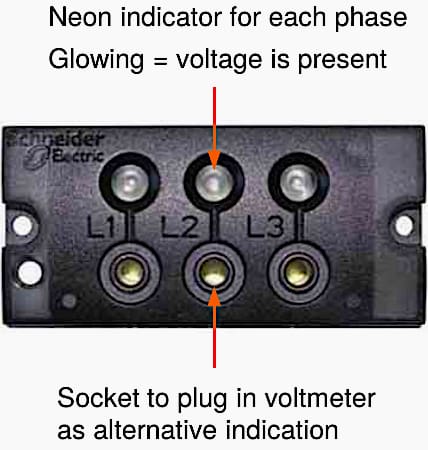
6. Voltage Indicators (Neon Indicators)
Voltage indicators are provided on the ring main unit front panel to show the electrical status of the associated cable. Earth switches must not be closed unless the indicators on each phase show the cable is de-energised. An example of voltage indicators is shown in Figure 12 below.
The markings L1, L2 and L3 represent the R, W and B phases respectively. The neon indicators glow to show the presence of voltage on each phase of the cable.
Some ring main units have removable voltage indicators. This facilitates proving the indicators are working on live circuits before and after switching to de-energise a cable.
Warning Note! Before applying an earth, the switching operator must use an approved testing method to positively prove the circuit is de-energised.
Figure 12 – Voltage presence indicating neon lights as fitted to a RM6 ring main unit
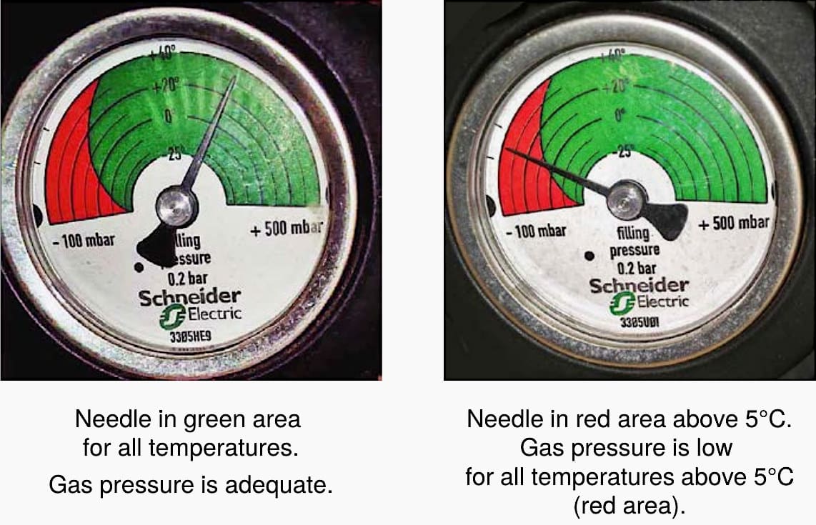
7. SF6 Gas Pressure Indicator
SF6 ring main units require adequate gas pressure at the operating temperature to achieve the rated switching current. An energised switch MUST NOT be operated with low gas pressure. The switching operator must check the gas gauge to ensure adequate pressure before operating a switch.
An example of a gas pressure gauge is shown in Figure 13. The gas pressure is indicated by the black needle. As pressure varies with temperature, the gauge has a number of concentric circles indicating temperature between the range of –25°C to +40°C. The green and red areas are used to show adequate or low gas pressure respectively.
For example, in Figure 13 the left-hand image shows the needle in the green area over the entire temperature range; therefore the gas pressure is adequate.
The right-hand image shows the needle crossing into the red area at an estimate 5°C from the concentric circles. This is interpreted as the gas pressure is low if the actual temperature of the switchgear (usually ambient temperature) is above 5°C (that is, a temperature in the red area).
Therefore if the actual temperature of the switchgear at the time of switching is above 5°C this switchgear must not be operated.
Figure 13 – Gas level gauge on RM6 ring main unit
Warning Note! Where RMUs are fitted with a gas pressure indicator, this indicator must be checked to ensure the gas pressure is adequate for the switch to be operated. Switching must not proceed if the gas pressure is outside acceptable limits.
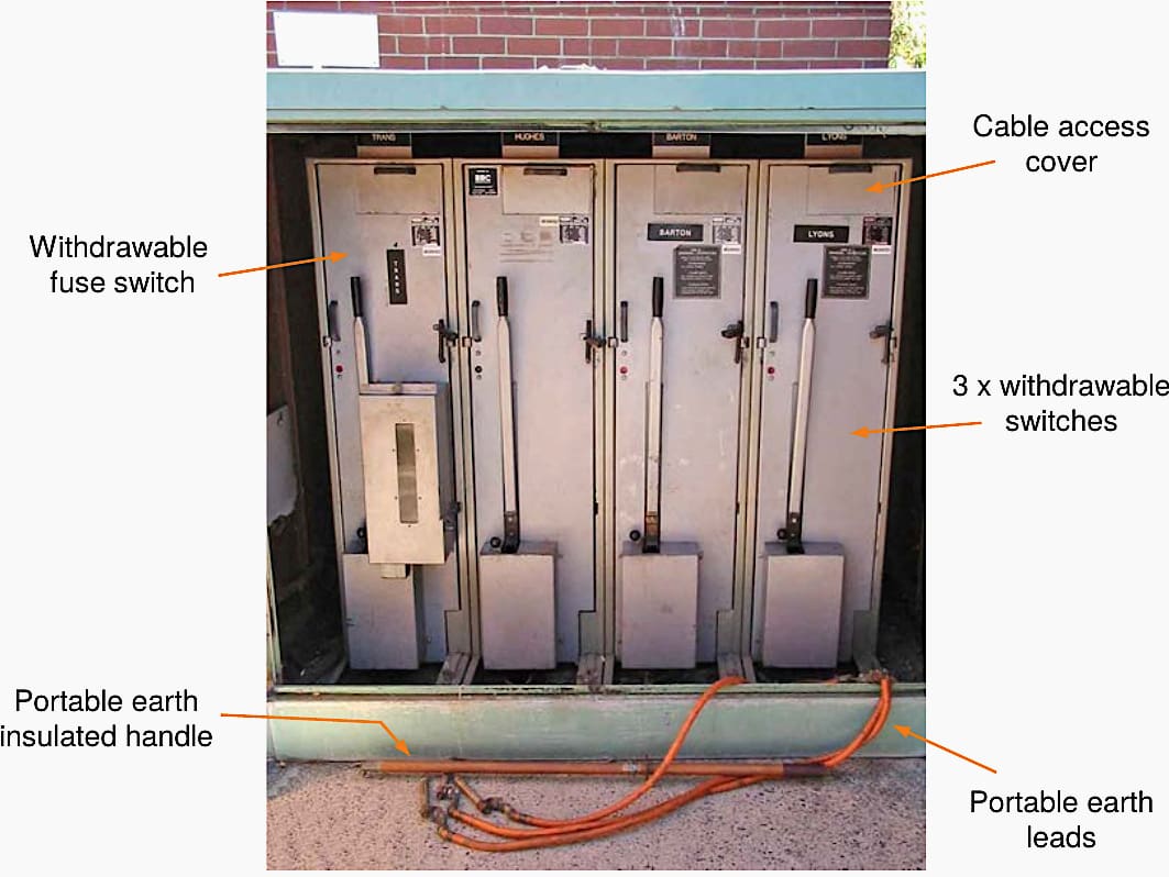
8. Earthing of Circuits Connected to Withdrawable Ring Main Units’ Switchgear
Withdrawable ring main units are not fitted with an integral earthing switch. Earthing of the cable circuits must be done manually. Earths must be applied as soon as possible after testing. If a circuit is proved to be de-energised, but earths cannot be applied at the time, the switching operator must prove the circuit is de-energised again, just before applying the earths.
An example of an old withdrawable ring main unit is the ABB unit (shown in Figure 14). Proving de-energised and earthing is performed through the cable access cover. The portable earths are applied with the insulated earthing handle.
Warning Note! Before applying an earth, the switching operator must use an approved HV testing device to positively prove the circuit is de-energised.
Figure 14 – An old ABB’s withdrawable ring main unit
9. Changing Fuse Switch Fuses
Fuse switches are used to supply distribution transformers. To change the fuses in the fuse switch the following conditions are required:
Condition #1 – The transformer must be isolated on the LV side – transformer LV disconnectors removed, barriers fitted and Danger–Do Not Operate (D–DNO) tagged.
Condition #2 – The fuse switch must be OFF and D–DNO tagged.
Condition #3 – The fuse switch earth switch must be ON – this earths both side of the fuses and enables access to remove covers and change the fuses.
Condition #4 – The fuse must be inserted with the fuse striker pin facing toward the trip bar.
Watch Video – RMU Components That Every Engineer Must Know – RMU FAT Test
10. Practical Course to Ring Main Unit and Medium Voltage Cables in Ring Power Distribution Systems
This course is dedicated to Ring Main Units, and medium-voltage distribution cables which are highly important for power distribution systems. The course covers the most significant aspects of ring systems and their role in different topologies of power systems and continuity of electrical feeding to consumers.
The cours econsists of 18 lectures in 4h 41m total length. English subtitles are included.
Students will learn what is the Load Break Switch (LBS), and what is the difference between LBS, Isolating Switch (IS) and Circuit Breaker (CB).
The course further explains the importance of Earthing Switch (ES) and the mechanical interlock.
Visit the Course
11. Attachment (PDF): Design Guide for Power Station Auxiliaries and Distribution Systems
Download: Design Guide for Power Station Auxiliaries and Distribution Systems (for premium members only):
Source: Switching Operator’s Manual by Horizon Power
Related electrical guides & articles


Edvard Csanyi
Hi, I'm an electrical engineer, programmer and founder of EEP - Electrical Engineering Portal. I worked twelve years at Schneider Electric in the position of technical support for low- and medium-voltage projects and the design of busbar trunking systems.I'm highly specialized in the design of LV/MV switchgear and low-voltage, high-power busbar trunking (<6300A) in substations, commercial buildings and industry facilities. I'm also a professional in AutoCAD programming.
Profile: Edvard Csanyi
