
Estimated Study Time: 39 minutes
Substation Control and Protection
Relay protection and the whole bunch of protection system engineering around the substation are quite interesting from the point of view of creativity. The Control and Protection System technology in a substation is very important because it watches over, protects, and manages the flow of electricity. Because substations are getting more complicated, more power is being sent, and fault currents are getting higher, which means that control and safety equipment has to work better.
 Practical Design Rules for Protection System Engineers
The main goals are to have the lowest possible life cycle costs and the most reliable service available. To get total reliability, it’s also important that the system is flexible and easy to manage.
To get low life cycle costs, it’s important to pick the right main equipment, whether to use AIS, GIS, or hybrid switchgear, the switching arrangement, the transformer size, and other things. Then decisions are made about the control and protection equipment, such as whether to use traditional or computerized control equipment, single or redundant protection systems, the design and voltage of the battery system, the type of battery to use, and so on.
Some general rules for Engineering of Protection System are given in this scientific article. These could be improved by the utility if it thought it was important based on its own needs and ways of doing things. SCADA systems control and watch, send signals, and record events most of the time these days. This article doesn’t talk about how to design a SCADA system.
- Engineering Of Protection System:
- Redundancy (Two Groups of Protection Systems)
- Instrument Transformer Circuits
- Physical Location of Relay Protection Panels
- Exchange of Information Between Two Subsystems:
- Arrangement of Trip Circuits
- Trip Unit
- Direct Trip of Remote End Breaker
- Trip Circuit Supervision
- Cabling
- Capacitive Discharges
- Alarming and Testing
- Design Of Fault Clearing System
- DC Distribution (Auxiliary Power System):
- Design Of Control and Protection Panel:
- Fault Signaling
- Interlocking
- Documentation
- BONUS! Download Guide for the Operation and Maintenance of Power Plant Equipment (PDF)
1. Engineering Of Protection System
1.1 Redundancy (Two Groups of Protection Systems)
In cases when there are two sets of direct current (DC) sources, the relays are electrically and physically split into two groups in order to achieve redundancy and facilitate the removal of a protection for maintenance purposes while the protected equipment is in operation. The process of grouping is implemented to the maximum extent feasible, ensuring that each group is capable of autonomously performing protective functions with almost equal redundancy.
The establishment of interconnection between these two groups is generally not recommended. Nevertheless, if it is absolutely essential, the level of linkage should be limited to the absolute minimum.
A common technique employed in redundant systems is:
- The utilization of redundant batteries is recommended.
- Two sets of safeguards are employed, each with the ability to fully execute the protective function.
- The objective is to achieve maximum physical segregation between the two groups.
- The instrument transformers employ distinct cores for the two protection groups.
- Due to budgetary considerations, the circuit breakers are not duplicated. The utilization of duplicated trip coils is observed.
- Cables should be arranged in distinct cable ducts or layers to the greatest extent feasible.
The breaker failure relay quantifies the residual fault current that remains flowing through the breaker following the anticipated tripping event, and subsequently triggers the tripping of all neighboring circuit breakers.
Figure 1 – Redundant power supplies within the central and bay units of the decentralized busbar protection

Figure 2 – Busbar protection power supply using two batteries and an auxiliary relay to commute between batteries
1.2 Instrument Transformer Circuits
In most cases, instrument transformers are not duplicated, but rather equipped with different cores to accommodate the two sub-systems. Various cores are interconnected with redundant protective methods. It is advisable to refrain from using a single current transformer core to supply power to both sub-systems. It is necessary to supply each Busbar protection with power from a separate CT core.
To mitigate the potential for open circuits at the terminating point or within the terminal itself, it is advisable to refrain from utilizing any current loop that supplies many panels. This precaution is particularly crucial when the loop is equipped with a disconnectable connection. Typically, both subsystems are linked to the identical CT junction box.
It is customary to have distinct secondary windings for the two sub-systems in voltage transformer circuits. In certain instances where two windings are unavailable, such as at lower voltage levels, it is advisable to employ distinct fuse groups within the marshalling box to divide the circuits. The high availability of voltage transformers renders this option generally acceptable.
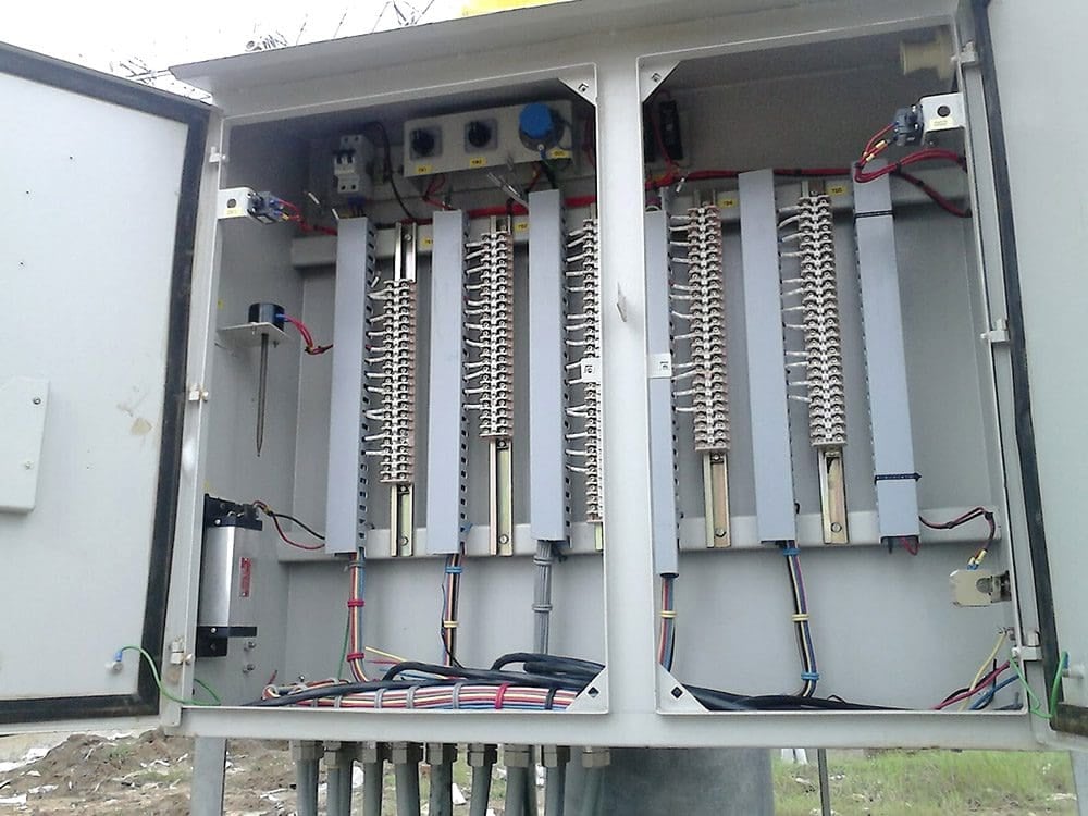
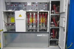
Figure 3 – Dedicated current transformer wiring panel in air insulated substation
1.3 Physical Location of Panels
The physical placement of the protection relays and auxiliary relays in the panels is crucial when utilizing sub-divided systems. It is recommended to employ distinct panels for the protection equipment of group A and group B. The rationale behind implementing physical split-up is to mitigate any issues that may arise from a singular incident, such as a cable fire or mechanical damage in a panel, affecting both sets of protective measures.
Additionally, it facilitates the ability to work on one group while the other group is engaged in service.
Nevertheless, in certain instances where the sub-systems occupy little space, it is deemed permissible to house the equipment for both sub-systems within a single panel. There is a little likelihood of cable fire or any other mechanical damage that may impact the two systems within the same panel. The issue of circuit mix-up resulting from errors during the processes of erection, commissioning, or maintenance necessitates careful consideration and the implementation of preventive measures.
Any equipment employed in the protective system, as well as additional supplementary relays linked to the identical battery system or fuse groups, must be consolidated and unambiguously designated. The equipment responsible for closing, interlocking, and other related functions is situated within the protection panel.
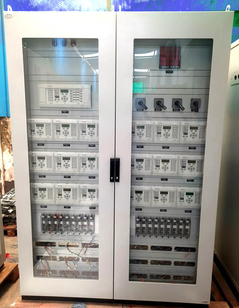
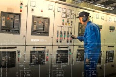
Figure 4 – Relay protection panel
1.4 Exchange of Information Between Two Subsystems
One of the primary principles employed in the utilization of sub-divided systems is to prevent signal exchange between the two systems. To the greatest extent feasible, sub-systems should function entirely autonomously from one another. This provides the utmost level of security during maintenance and other related activities, encompassing both human and equipment failures.
Nevertheless, in the majority of instances, certain signals are necessary to be transmitted to another sub-system. The signals that are most frequently encountered are:
1.4.1 Start and Block of Auto-Recloser
The duplication of auto-recloser is typically avoided due to speed limitations associated with two units, as well as the absence of significant consequences resulting from a failure to autoreclose.
The sub-systems involved in the initiation and termination of the autoreclose function engage in the exchange of various signals.
Further Study – Auto-reclose schemes for re-energising the line after a fault trip
Auto-reclose schemes for re-energising the line after a fault trip
1.4.2 Start of Breaker Failure Protection
The Breaker failure relay/function (BFR) isn’t duplicated in redundant systems, just like the Auto-recloser function. However, the rationale behind this is entirely different. The Breaker failure function necessitates stringent security measures to prevent unnecessary trippings and duplication, resulting in enhanced dependability but a deterioration in security.
Given the statistically low risk of breaker failure, prioritizing security is of greater significance.
The provision of the BFR function is limited to a single system, often within the Group A protection system. It is now usual practice to provide DC changeover to the BFR relay when using a single BFR, as this enhances reliability and availability. When the breaker failure function is repeated, such as when duplicate busbar protection is employed, it is important to acknowledge the associated security issues.
In order to facilitate the identification and disconnection of the appropriate terminals during the separation of sub-systems, it is imperative that the terminals are prominently displayed within the panel.
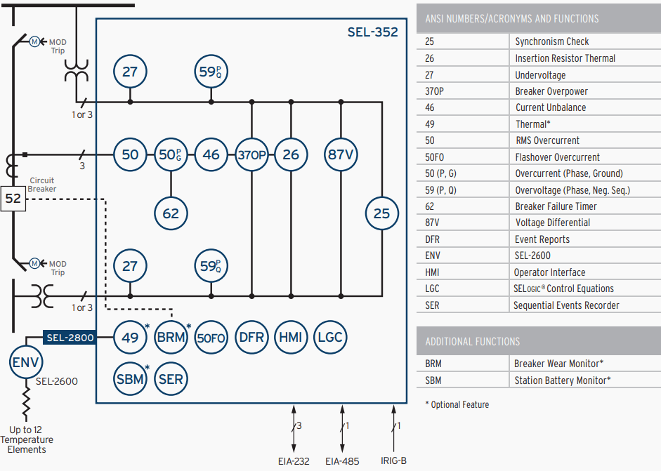
Figure 5 – Functional diagram of a Breaker Failure Relay
1.5 Arrangement of Trip Circuits
The trip circuits are a significant component of the protective system. The occurrence of a trip circuit failure will inevitably result in the failure to activate the circuit breaker. As previously stated, the breaker is not duplicated due to cost considerations. The only practical way to enhance reliability is by incorporating two trip coils on the breaker.
This approach aims to mitigate operational failure issues related to DC supply, wiring, and trip coils in CBs. However, it does not provide any benefits in terms of mechanical issues within the CB operating mechanism.
Related electrical guides & articles


Edvard Csanyi
Hi, I'm an electrical engineer, programmer and founder of EEP - Electrical Engineering Portal. I worked twelve years at Schneider Electric in the position of technical support for low- and medium-voltage projects and the design of busbar trunking systems.I'm highly specialized in the design of LV/MV switchgear and low-voltage, high-power busbar trunking (<6300A) in substations, commercial buildings and industry facilities. I'm also a professional in AutoCAD programming.
Profile: Edvard Csanyi
