
Estimated Study Time: 29 minutes
Introduction to Secondary Equipment
The design of the high-voltage substation must include consideration for the safe operation and maintenance of the secondary equipment. The substation secondary systems are those systems which provide the functionality necessary to ensure safety of personnel engaged in operation of the substation and associated systems. On the other side, such systems permit operation of the substation primary circuits.
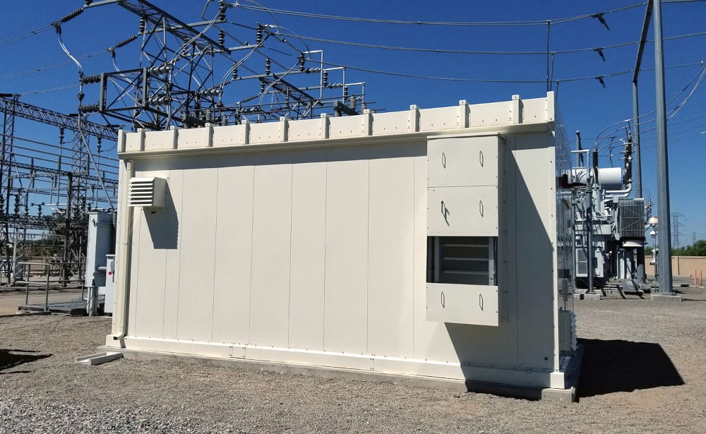
 Installation Precautions for Substation Secondary Equipment (on photo: Back side of the protection panel doors; photo credit: Crown Technical Systems)
They also monitor the performance of the installation and each piece of substation equipment. The role of secondary systems is also to detect and manage abnormal conditions on the system and in primary equipment, as well as to manage the environment in which the equipment operates.
This technical article discusses some of the most important aspects which need to be considered to ensure the effective performance of the secondary system in a power substation.
- Cubicles and Rooms MUST be Separated
- DC Distribution Supply
- Relay Rooms or Switchyard Houses:
- Cabling and Wiring:
- Secondary Equipment and Ventilation Accommodation:
- Fire Detection and Extinguishing:
- Attachment (PDF) 🔗 Download ‘Step-by-Step Manual for Starting a Load-Flow Study and Power System Analysis’
1. Cubicles and Rooms MUST be Separated
Per Substation level or bay level
In a substation, the secondary equipment provides the functional interface for the control, supervision, and protection of the network. The equipment is organized into substation level or bay level depending on whether it operates on an overall substation basis or only for a single bay.
The secondary equipment can be located in different buildings or in separate rooms within a central building or in some cases, mounted directly adjacent to the switchgear.
For high-voltage open-air substations and for high-security, metal-clad substations, the usual practice is to provide dispersed relay kiosks/rooms for bay-level equipment and a centralized control building for substation-level equipment.
Figure 1 – Relay kiosks for bay-level equipment
2. DC Distribution Supply
Without ANY Interruption
Substation secondary equipment must be powered by sources which are not subject to interruption at times of AC power faults. This requirement is met by the use of battery systems kept in a fully charged condition by battery chargers supplied from the AC network.
Inverter systems operating from a battery give a similar level of security to equipment powered by AC.
Each DC system includes a battery, a charger, and a distribution board. They may be located in the same ventilated room, if sealed gas recombining cells are used. This has the effect of minimizing the length of cables between the battery, the charger, and the distribution board and also simplifies maintenance. Hydrogen-releasing batteries, due to the risk of explosion, must be located in a separate room closed by means of a self-closing door.
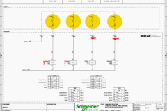
Duplicate DC systems are generally employed for substations rated 220 kV and above, to ensure availability, security, and reliability.
Figure 2 – Typical doubled battery and charger application
The DC distribution board is fed in parallel by the battery and charger. This indicates that to compensate for voltage loss, the direct current voltage supplied to the loads is generally 10–12% greater than the nominal battery voltage; for instance, a 110 V battery corresponds to approximately 125 V under normal conditions.
Furthermore, when operating on battery power solely, the minimum voltage at the circuit breaker must be sufficiently adjusted to trigger the trip coils. Standard tolerances are +10% and 20%. Consequently, the battery voltage must be maintained at a level that guarantees this.
It is typical to implement a method of earth fault detection. A conventional design involves connecting a high resistance in parallel with the battery terminals, with the midpoint of the resistor linked to the ground via an earth current monitor.
Thus, a single fault is readily identified prior to the emergence of a more severe double fault and the potential for a short circuit.
Video Lesson – Earth fault protection (ANSI 50/51N)
It is essential to check out the effects on cathodic protection systems, which mitigate corrosion on metallic structures, when selecting ways for earthing the DC system during the design phase. Impressed current cathodic protection (ICCP) systems employ an injected (anode) current that may experience interference based on the chosen method of battery earthing.
A substation may comprise multiple DC systems. Each system comprises a battery, charger, distribution board, and corresponding wiring. If sealed gas recombining cells are employed, they may be situated in the same room. This reduces linking cable between the battery charger and the board, hence simplifying maintenance.
Nevertheless, if hydrogen-releasing cells are utilized, the batteries must be situated in a separate room equipped with a fire-resistant door due to the potential of explosion. The latter will necessitate an acid-resistant floor in the battery room.
Cables with flame-retardant insulation or covering are utilized to mitigate the possibility of damage escalation during a fire.
Good Reading – Are your switchgear and electrical room safe?
3. Relay Rooms or Switchyard Houses
Must be Near Primary Equipment
Protective and control equipment may be located in a central building and/or in dispersed relay kiosks/rooms. With GIS and AIS at lower voltages (or where the primary plant is erected indoors), distances between primary and secondary equipment are short and favor a centralized arrangement for the protection and control equipment.
The practice is to use single vertical panels , especially for distribution circuits with limited spatial requirements. The relaying, metering, and control devices can be installed onto a single panel, designating an individual panel for each circuit. In certain cases, two circuits may utilize the same panel.
The prevailing trend favors more compact equipment configurations, which often results in a reduction of the overall size of the control house or room.
The arrangement adopted depends in each case on such factors as:
- The physical size and layout of the HV plant (voltage level, AIS or GIS, etc.).
- The requirements for secure operation and maintenance and the risk of a common mode failure in case of fire.
- The type of control equipment employed (traditional or computer based) and type of internal connections (cables or optical fibers).
- The cabling from VT and CT to the secondary equipment. Lead burdens must be limited to values which permit the correct functioning of the equipment.
- Environmental conditions (adverse climatic conditions can make it desirable to group the secondary equipment within a common central building).
- The overall cost of installation.
- Building – cabling and wiring.
- Heating/cooling equipment – installation.
Figure 3 – 115 kV indoor GIS layout
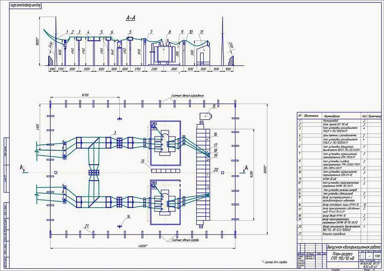
Figure 4 – A typical switchyard layout plan
3.1 Group A and Group B Protection Systems
When two sets of DC sources are installed, relays are electrically and physically divided into two groups to ensure redundancy and facilitate maintenance without interrupting service to protected equipment. Grouping is carried out to maximize the capacity for each group to independently perform protective operations that have comparable redundancy.
The interconnection between these two groups shall normally be avoided. Nonetheless, if deemed essential, such interconnection shall be restricted to the minimum required.
Related electrical guides & articles


Edvard Csanyi
Hi, I'm an electrical engineer, programmer and founder of EEP - Electrical Engineering Portal. I worked twelve years at Schneider Electric in the position of technical support for low- and medium-voltage projects and the design of busbar trunking systems.I'm highly specialized in the design of LV/MV switchgear and low-voltage, high-power busbar trunking (<6300A) in substations, commercial buildings and industry facilities. I'm also a professional in AutoCAD programming.
Profile: Edvard Csanyi
