
Estimated Study Time: 22 minutes
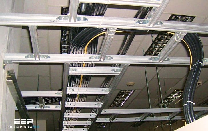
Energy transport via cables and busbars
First, to be clear, there are dozen of concerns and precautions you should be aware of when we talk about energy transport. Cables and busbar systems are the most common and reliable ways to do so, at least until wireless energy transport is developed :) However, many potential issues need to be addressed. This article deals with four significant precautions you should take – grouping conductors in parallel, short circuits, magnetic effects, operating current, and voltage drop.
 Four very important precautions for the installation of cables and busbar trunking systems
If you ask me, I will always prefer the prefabricated busbar trunking systems over cables, where possible, of course. There is no rule for such a statement, but if you can choose and have the financial support – go for prefabricated busbars. Pay more for reliable power transport and less headache.
Ok, let’s address these three critical precautions for the installation of cables and busbar trunking systems.
- Grouping conductors in parallel
- Precautions for short circuits
- Precautions with respect to magnetic effects
- Operating current and voltage drop
1. Grouping conductors in parallel
Above a certain current (usually several hundred amperes), the use of several conductors in parallel allows their cross-section to be limited and thus their handling made easier. This technique, very often used for the conductors between the transformer and the main low voltage switchboard, is also used for high-power outgoing connections.
The use of prefabricated busbar systems is, however, recommended.

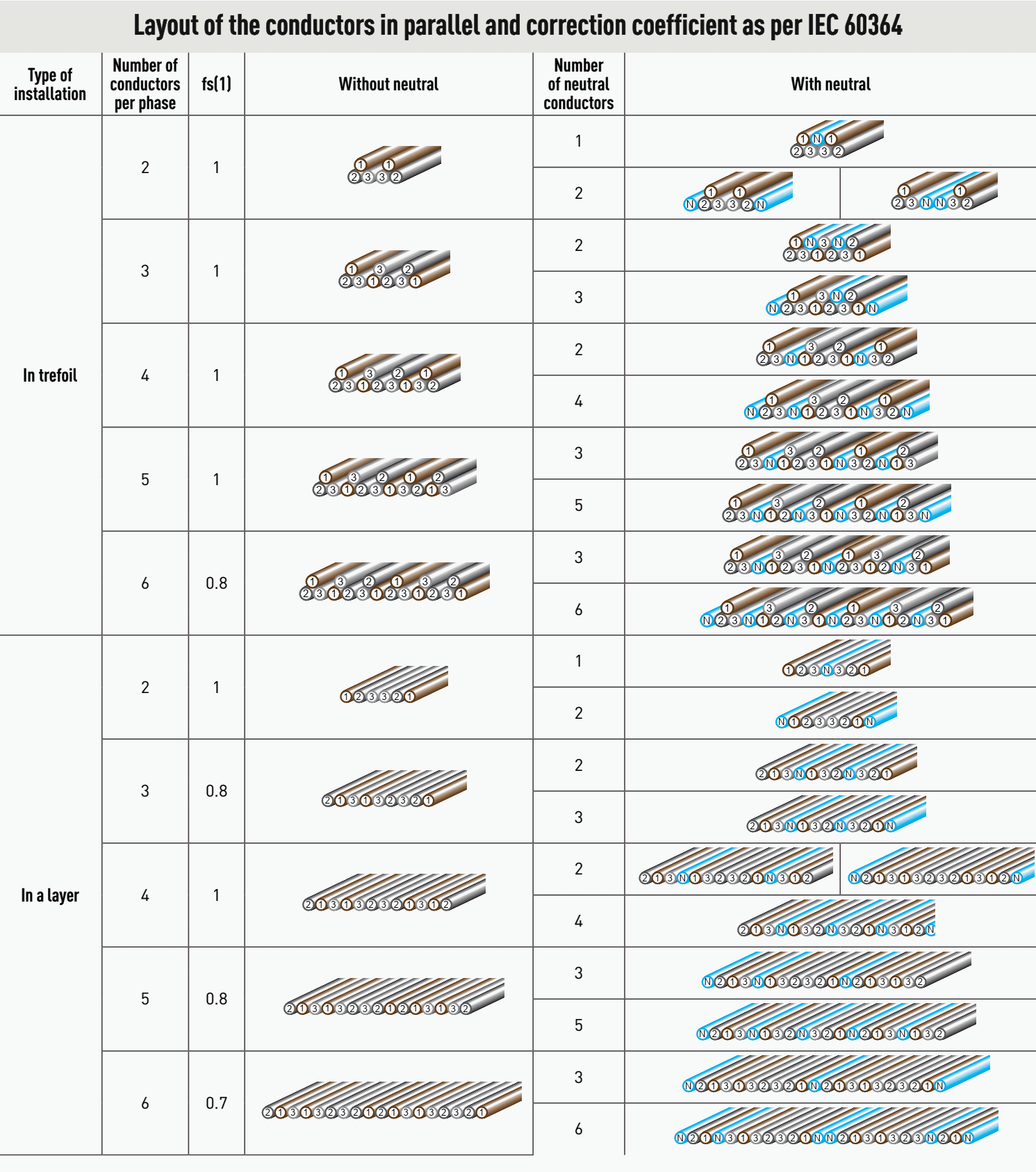
The arrangement of conductors in a triangle (or in a trefoil) provides the best balance, but is generally limited to two or even three conductors per phase. Above this, the overlapping of layers limits cooling and installation in a bundle is preferable.
This proximity rule also applies to single conductors (phases, neutral and protective conductor).

3-phase distribution via the conductors in parallel must comply with the strict geometrical layout rules. This also supposes that all the conductors are of the same type, same cross-section and same length and that they do not include any tap-off in their route and cannot be supplied individually.
In the event of failure to comply with any one of these conditions, the overall protection of the bundle of parallel conductors by a single device would not be possible; one protection device per conductor would then be necessary. It is recommended that the number of parallel conductors is limited as far as possible.
Above four cables, it is preferable to use prefabricated busbar systems, providing a better distribution of currents.
Table 1 – Layout of the conductors in parallel and correction coefficient as per IEC 60364
1.1 The theory behind rules
With alternating current, electrical conductors have an impedance (expressed in Ohms) which is the complex function of three factors:
- Resistance R (also called ohmic resistance),
- Reactance Lω due to the self-inductance of the conductor, and
- Capacitance 1/cω (or capacitive reactance) due to running conductors together, which creates a capacitor.
The illustration opposite is given for a phase shift of 45° (cosϕ = 0.5). Resistance and reactance equal. It should be noted that, for these currents, the capacitance component can be ignored.
Self-induction or own inductance coefficient (L)
It determines the electromotive force “e” circulating in a conductor following the variation in magnetic flux (Φ) surrounding the conductor. The conductor’s inductance depends on the material’s magnetic characteristics, the medium and its geometry (length, number of turns):
e = −L × dΦ/dt
Mutual inductance
For a symmetrical link, the self-induction coefficient is perceptibly identical for each conductor, this is:
L = (0.05 + 0.46 log d/r ) in mH/km.
where: d is the average distance between the axes of the conductors, and r is the radius of the core of the conductor.
In an asymmetrical arrangement, since the distances are different, the mutual inductances between conductors will also be different. From this, it follows that the distribution of the current will be asymmetrical.

Application to conductors in parallel
The equal distribution of currents in several identical conductors in parallel is uniquely linked to the equality of the impedances in each of the conductors. With the inductance proportion becoming dominant with the increase in section, the geometrical layout of the conductors will dominate (identical distances for each of them).
Three-phase layout
In a cable or bundle of conductors in 3-phase (with or without neutral), the vectoral sum of the currents is nil and the resulting magnetic induction created by the conductors remains very low if they are grouped together and arranged in a regular pattern. If this is not the case, the self-induction coefficient of the conductors will be modified by the interaction of the magnetic field created.
Own and mutual inductances and the distribution of the currents will then be out of balance.
2. Precautions for short circuits
There are two destructive effects which can affect conductors in the event of a short circuit:
- Thermal stress, protection against which is normally provided by the limiting power of the protection devices (fuses, circuit breakers)
- Electrodynamic stresses, whose forces between conductors can have destructive effects.
2.1 Conductors in cable tray
When a short circuit between two active conductors occurs (the most probable), the conductors suffering the intense current of the short circuit will be repelled with a force proportional to the square of the intensity. If they are poorly secured, they will start to whip and could tear out of their ties and touch another conductor or an earth causing a new short circuit with a highly destructive arcing effect.
Multi-conductor cables are designed to withstand the forces that could be exerted by these conductors.
The indications given below, intended to draw attention to the importance of holding conductors securely, cannot by themselves guarantee that short circuit conditions will be withstood. These will require test simulation.
Table 1 – Wiring precautions for presumed short circuit values
| Value of presumed short circuit | Wiring precautions |
| Isc ≤ 10 kA | No specific precautions. |
| 10 ka < Isc ≤ 25 kA | Conductors must be attached using cable ties. Wires for a single circuit may be twisted together |
| 25 ka < Isc ≤ 35 kA | Conductors in a single circuit must be held separately and attached singly. If they are twisted together, the number of cable ties should be increased (one per 50 mm length). |
| 35 < Isc ≤ 50 kA | Conductors in a single circuit must be attached singly on a non-damaging rigid support (cross-piece, profile). They are physically separated. Each attachment point comprises two crossed cable ties. |
| Isc > 50 kA | At these short circuit values, forces become such that the securing means must be specially designed: machined cross pieces and threaded rods, for example. |
2.2 Prefabricated busbar trunking
Even if there are few limitations in the use of prefabricated busbar trunking, it is still important to check that its short circuit resistance characteristics are actually coordinated with its upstream protection devices.
The trunking must be able to withstand the thermal stress associated with the short circuit for the entire duration of the fault, i.e. for the whole of the time necessary for the protection device (circuit breaker) to trip. Similarly, the electrodynamic forces permitted by the busbar trunking must be compatible with the peak current limited by the upstream protection.
The presumed peak value (Ipk), can be determined by reading devices’ limiting curves or in the absence of data, by applying an asymmetry factor n (see Table 2 below) at the effective value of the short circuit current (Isc).
Table 2 – Effective values of the short circuit and applied asymmetry factor
| Effective value of the short circuit | cos ϕ | n = ipk/i |
| I ≤ 5 kA | 0.7 | 1.5 |
| 5 ka < I ≤ 10kA | 0.5 | 1.7 |
| 10 ka < I < 20kA | 0.3 | 2 |
| 20 ka < I ≤ 50kA | 0.25 | 2.1 |
| I > 50ka | 0.2 | 2.2 |
As with trunking made up of conductors and cables, presumed short circuit current calculations and the determination of protection devices must be done prior to any installation.
Further reading…
3. Precautions with respect to magnetic effects
Passing high currents through conductors induces magnetic effects in adjacent metallic masses, which can result in the unacceptable heating of the materials.
Few wiring precautions are therefore essential.
- To reduce the induction created, it is necessary to arrange the conductors so that the field is as weak as possible. So far as is possible, conductors should be arranged in a trefoil to reduce induced fields (see diagram for grouping conductors above).
- To prevent significant heating in cable tray sections, it is advisable to remove the parts that create loops around a conductor.
- Breaking the magnetic loop by removing sections is also possible. In all cases, check that the mechanical strength remains acceptable.
- Cutting wire cable tray in order to prevent magnetic fields likely to cause heating.

3.1 Magnetic loops
In order to minimise the induction created in magnetic loops, it is still recommended that all the life conductors in a circuit (phases and neutral) should be positioned within the same metal (steel) compartments.
Since the vectorial sum of the currents is nil, the one of the fields created is too.
The circulation of a current I in a conductor creates a proportional field H , the effect of which is to create induction B in the surrounding medium. The value of B depends on the value of the field (therefore on the current) but also on the magnetic characteristics of the medium or the material. It is the magnetic permeability µ expressed in henries per metre (H/m).
Ferrous materials (steel) being magnetic by nature, are particularly likely to conduct fields but also to become saturated if these fields are too high.
4. Operating current and voltage drop
4.1 Prefabricated busbar trunking
To calculate the actual current that will allow the choice of the busbar trunking, a certain number of data must be known:
- The type of supply: 3-phase or single phase,
- The configuration of the supply to the trunking: from one end, from both ends, from the middle, etc.,
- The rated supply voltage,
- The number, power and cos ϕ of the loads that must be supplied by the trunking,
- The load simultaneity factor,
- The load use factor,
- The presumed short circuit current at the supply point,
- The ambient temperature, and
- The layout of the bars in the trunking (on edge, flat, vertical).
For a 3-phase supply, the actual operating current is determined by the formula:
where:
- IB = operating current (in a)
- PTOT = total active power installed (in W)
- Kc = simultaneity factor
- Ku = usage factor
- d = supply factor, determined as follows :
- 1 when the trunking is supplied from one end;
- 0.5 if it is supplied from the middle or both ends
- Ue = operating voltage (in V)
- cos ϕ = average power factor.
The trunking will be chosen using the rated current immediately above the calculated current. The rated current applies to a specific orientation of the trunking. However, the influence of the orientation may be ignored for short vertical sections in horizontal trunking (less than 3m long, for example).
4.1.1 Losses through Joule effect
Losses through the Joule effect are essentially due to the electrical resistance of the bars. lost energy is transformed into heat and contributes to the heating of the trunking.
- For three-phase: P = 3 × Rt × IB2 × 10−3
- For single-phase: P = 2 × Rt × IB2 × 10−3
where:
- P = dissipated power per unit of length (in W/m)
- Rt = linear resistance of phase bars measured at thermal equilibrium (in mΩ/m)
- IB = operating current (in A)
4.1.2 Voltage drop
If the trunking is particularly long (≥ 100m), it is necessary to check the voltage drop. According to standard IEC 61439-6, the voltage drop in 3-phase trunking may be calculated using the following formula:
u = k × √3 × (R × cosϕ + X × sinϕ) × IB × L
where:
- u = system composite voltage drop (in V)
- R and X = averages of the resistance and the reactance, (in Ω/m)
- IB = current of the circuit considered (in a)
- L = length of the circuit considered (in m)
- cos ϕ = power factor of the circuit considered
- k = load distribution factor, calculated as follows:
- To calculate the voltage drop at the end of the trunking:
- k = 1 if the load is concentrated at the end
- k = (n + 1)/2n if the load is uniformly distributed between n tap-offs
- To calculate the voltage drop at a tap-off situated at a distance d from the origin point of the trunking:
k = (2n + 1 − n×d/L)/2n if the load is uniformly distributed between n tap-offs
- To calculate the voltage drop at the end of the trunking:
To simplify the calculations, every manufacturer indicates in the tables the characteristics and unit voltage drop K, according to the values of cos ϕ. The voltage drop at the end of the trunking can then be calculated using the following formula:
u = b × K × L × IB × 10−6
where:
- u = the voltage drop (in V)
- b = the current distribution factor depending on the way in which the circuit is supplied and the distribution of electrical loads along the trunking (see table below)
- K = the unit voltage drop (in µV/m/a) for a given cosϕ
- IB = the operating current in the trunking (in a)
- L = the length of the trunking (in m)
Table 3 – Current distribution factor “b”
| Current distribution factor “b” | |
| Supply from one end and load at the other end of the trunking | b = 2 |
| Supply from one end and uniformly distributed loads | b = 1 |
| Supply from both ends and uniformly distributed loads | b = 0.5 |
| Supply from the middle of the trunking and loads at its ends | b = 0.5 |
| Supply from the middle of the trunking and uniformly distributed loads | b = 0.25 |
4.2 Cables fitted in cable trays or ducts
The use of cable tray systems for power distribution requires detailed knowledge of electrical installation characteristics. For installations with long runs, it is particularly important to check voltage drops.
If the voltage drop is greater than the permitted limit, it will be necessary to increase the section of the conductors until the voltage drop is less than the prescribed value.
4.3 Supplying motors
If the installation supplies motors, it is advisable to check the voltage drop under start-up conditions. To do this, simply replace current IB in the formula opposite with the starting current of the motor and use the power factor on starting. in the absence of more accurate data, the starting current can be taken as being 6 × In.
The voltage drop, taking into account all the motors that may start at the same time, must not exceed 15%. apart from the fact that too high a voltage drop can hinder other users of the installation, it may also prevent the motor starting.
Further calculations in the form of MS Excel spreadsheet:
Sources: Legrand,
Related electrical guides & articles


Edvard Csanyi
Hi, I'm an electrical engineer, programmer and founder of EEP - Electrical Engineering Portal. I worked twelve years at Schneider Electric in the position of technical support for low- and medium-voltage projects and the design of busbar trunking systems.I'm highly specialized in the design of LV/MV switchgear and low-voltage, high-power busbar trunking (<6300A) in substations, commercial buildings and industry facilities. I'm also a professional in AutoCAD programming.
Profile: Edvard Csanyi

Please supply white paper.
In grouping conductors in parallel between transformer and low voltage panel , Which is the better On the one hand of the number of the single cable in the phase (one circuit)؟ , For example , 3 X(4*240mm2) three groups or 4x (4*150mm2) four groups .Regardless of the value of the current.
thank you
Hello, I have just come across this article and found most of the answers to my question with just one exception. Section 1 addresses the importance of grouping conductors in parallel. However, section 4.3 does not mention if the requirement to maintain grouping in parallel within underground ducting should or must be ensured?
Bs in physics, ibew instructor, i would keep them grouped in non metallic raceways as well. The magnetic fields of the wires exert force on one another, not just the raceway. My 2 cents
Your notes is very very important and so educative. I have learned alot from your technical articles.
Thank you for your support in consideration of my interests in major questions of busbar and cable system
Marvelous professional paper
Great, Edvard, Congratulations