
Installation configuration
The term installation configuration, when applied to prefabricated busbar systems and cables – power transport and power distribution in the installation, essentially refers to the geometric requirements of the conductor routing that will have to be taken into consideration.
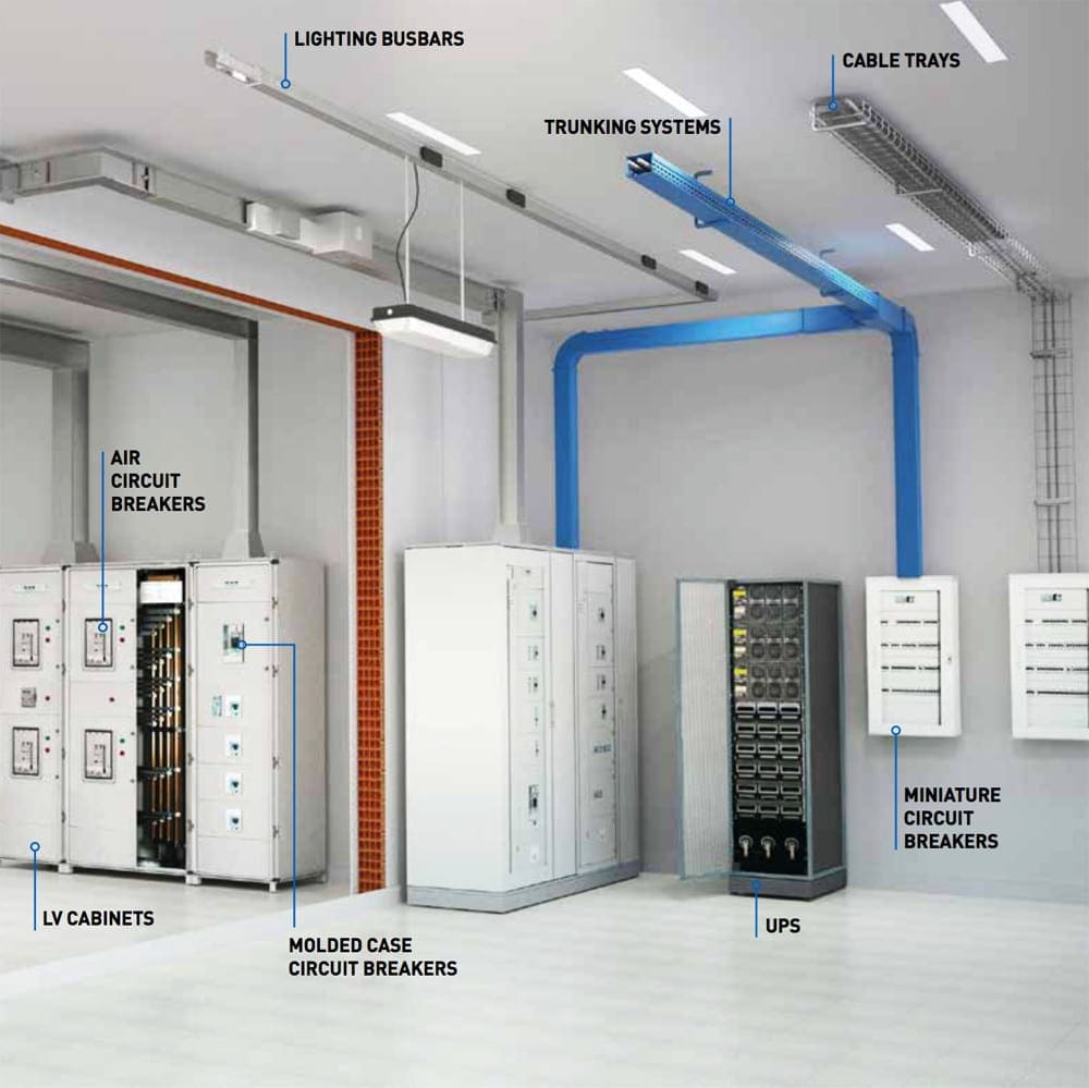
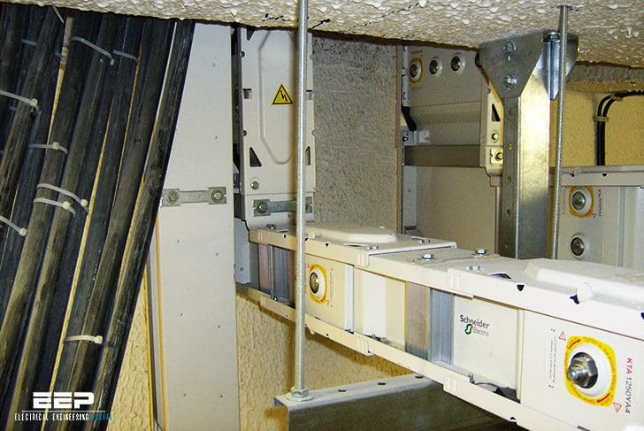 Installation tips for prefabricated busbar systems and cables (on photo: Example of high power distribution; credit: Edvard CSANYI)
Adaptability requirements may also be added to these considerations, particularly at the level of connection of usage points which must have the required flexibility (for example frequent disconnections or changes).
1. Conductor rating
To design a power transport system with prefabricated busbar systems or cables, it is necessary to have an overall vision of the routing to be achieved, paying particular attention to changes of direction, obstructions (partitions, fire breaks, doors, etc.) or obstacles (pillars, walls, etc.), which must be avoided without any interruption in the continuity of the conductors.
The choice of a cable tray or prefabricated busbar system must be compatible with the routing required, without forgetting to check that the accessories necessary for changes of direction,to avoid obstacles, for alterations of level and feedthroughs are actually available.
Moreover, it is necessary to give consideration to the characteristics of the floor tiles or the walls (for example reinforced concrete), the difficulty in securing supports, as well as the size and weight of the cable trays or prefabricated busbar systems.
Go back to installation tips ↑
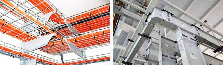
1.1 Cable trays or prefabricated busbar systems?
These two systems are used in the infrastructure for transporting and distributing electric power, regardless of the destination:
- Industrial or commercial sites,
- Service sector establishments or
- Residential buildings.
The existence of numerous types of conductors suitable for the majority of stresses (temperature, immersion, chemical substances, vegetation, fire, uV, etc.) means that cable trays can be installed in almost any environment. The limit on this system is a result of the maximum operating current (multiple conductors) or the electrical requirements (short circuit and magnetic radiation).
Prefabricated busbar systems are both an alternative and a complementary system. Conductors are grouped together and isolated in the same enclosure, which supports and protects them.
These integrated systems, perfectly calculated from an electrical and electromagnetic point of view, allow the flow of very high power and give very high levels of protection against specific stresses: IP, fire, electromagnetic radiation. Integrating them into the infrastructure of the building requires preliminary consideration to ensure that optimum solutions are selected. specific rules must be followed for installation and assembly.
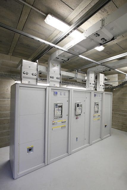
Prefabricated busbar systems are generally classified as “high power”, “medium power” and “low power”. They allow all types of power transport from the power source to the end usage point (workstations, machines, lighting, etc.).
Cable trays and prefabricated busbar systems are two different systems, each with its own advantages. Of course, their use can also depend on common practice. Naturally, the two systems are complementary and can be installed at different levels, or for different usages at the same site.
With a global approach to conductor routing, it is also necessary to consider the other services in the building that could be an interference:
- Water,
- Gas,
- Smoke conduits or ventilation,
- Air conditioning,
- Fire systems and
- Other networks in general.
Some sensitive sites (airports, data centres, high technology industries, etc.) require a second duct for power transport and distribution which must be separate for the safety of property and people, with the aim of ensuring continuity and/ or segregation in the case of a fire risk.
Go back to installation tips ↑
1.2 Dimension and size of the distribution system
The height and the width of the ducting chosen must be suitable to contain the cable bundles, potentially in several layers.
It could be necessary, for example, to choose narrow cable trays or trunking with high sides for long runs, or wide cable trays or trunking with low sides to install cables in a reduced number of layers.
In every case, there must be a study to facilitate the installation of trunking and laying of cables. If the space available is limited, it is interesting to examine a “prefabricated busbar system” solution which generally offers more compactness.
Go back to installation tips ↑
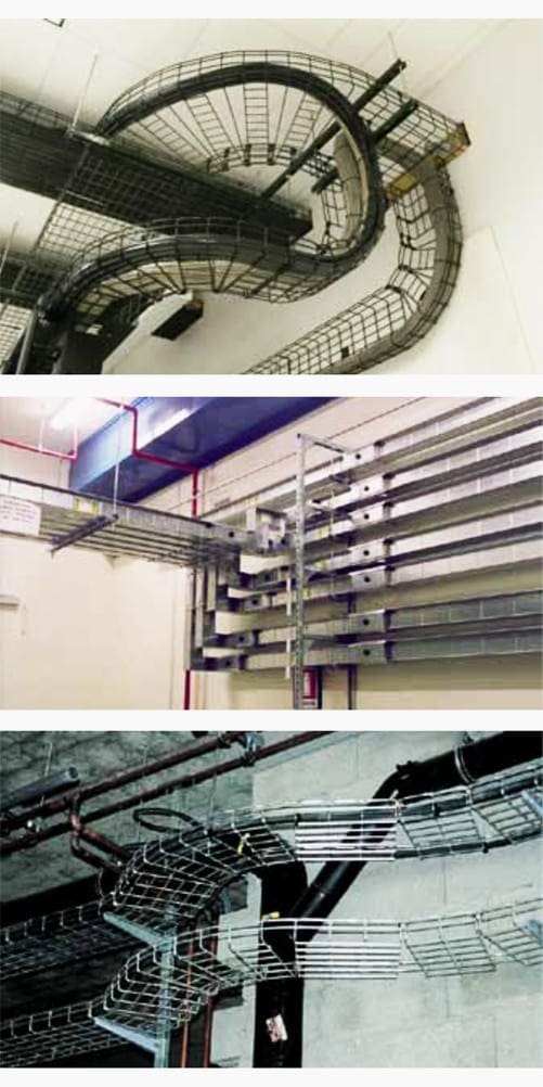
1.3. Bend radius
The minimum bend radius can be a limitation on the installation and this must be taken into account. It depends on the cross-section of the cables and the number of cables that must be installed without stress. Planning for a minimum bend radius at least equal to 6 or 8 times the exterior diameter of the largest cable is recommended.
Prefabricated busbar systems have special parts (elbows) which allow less cumbersome changes of direction than are possible with trunking and cable trays.
Go back to installation tips ↑
1.4. Mechanical resistance
The conduit must be capable of supporting the weight of the cables it contains. It is necessary to check the maximum load certified by the manufacturer and to comply with it strictly. Ducts for heavy loads can allow a reduction in the number of supports, whereas light ducts will require numerous fixing points.
Prefabricated busbar systems are self-supporting solutions that give more rigidity to the installation. It is particularly important to check the availability of all the parts and accessories needed to create the links, down to the smallest detail.
Go back to installation tips ↑
1.5. Specific installation requirements
In addition to the requirements of sizing, fitting shape and mechanical resistance related to conductor routing, each installation situation generally requires the study and implementation of particular precautions.
In the majority, these precautions are connected with the local environmental conditions, classified in the broadest sense by the standards bodies as “external influences”. These conditions, defined by standard IEC 60364-5-52, characterise mechanical stresses (impact, vibration, earthquakes, etc.), climatic stresses (temperature, humidity,etc.) to which are added a certain number of specific stresses, such as wind, sun, corrosion, fire risk, etc.
Go back to installation tips ↑
2. Level of flexibility of the installation
The choice of a power transport system in a building must also allow for any potential modifications, developments and extensions of the installation.
Ease of installation is also important in order to minimise the time required to modify the system and to ensure quick and safe maintenance. With this in mind, the choice must take into consideration operations that could affect the production costs or management of the system.
As the installation evolves, prefabricated busbar systems guarantee continuity of service by allowing connections and disconnections with the power on. On the other hand, it can be less costly to install trunking or cable trays in installations that do not require any particular modifications or maintenance.
Go back to installation tips ↑
3. Connections and junctions
The electrical installation must be designed and installed taking into account the need for modification and extension. This means that a flexible system must be installed, which must allow connections to power future uses.
Cables and prefabricated busbar systems must be sized to take account of possible extensions and must allow new junctions. With a “cable” solution, connection equipment, such as distribution boxes and panels, must be installed at pre-defined points along the main line.
This equipment, which could potentially be fitted with protection or isolation devices, will be able to power the starting points of the additional lines.
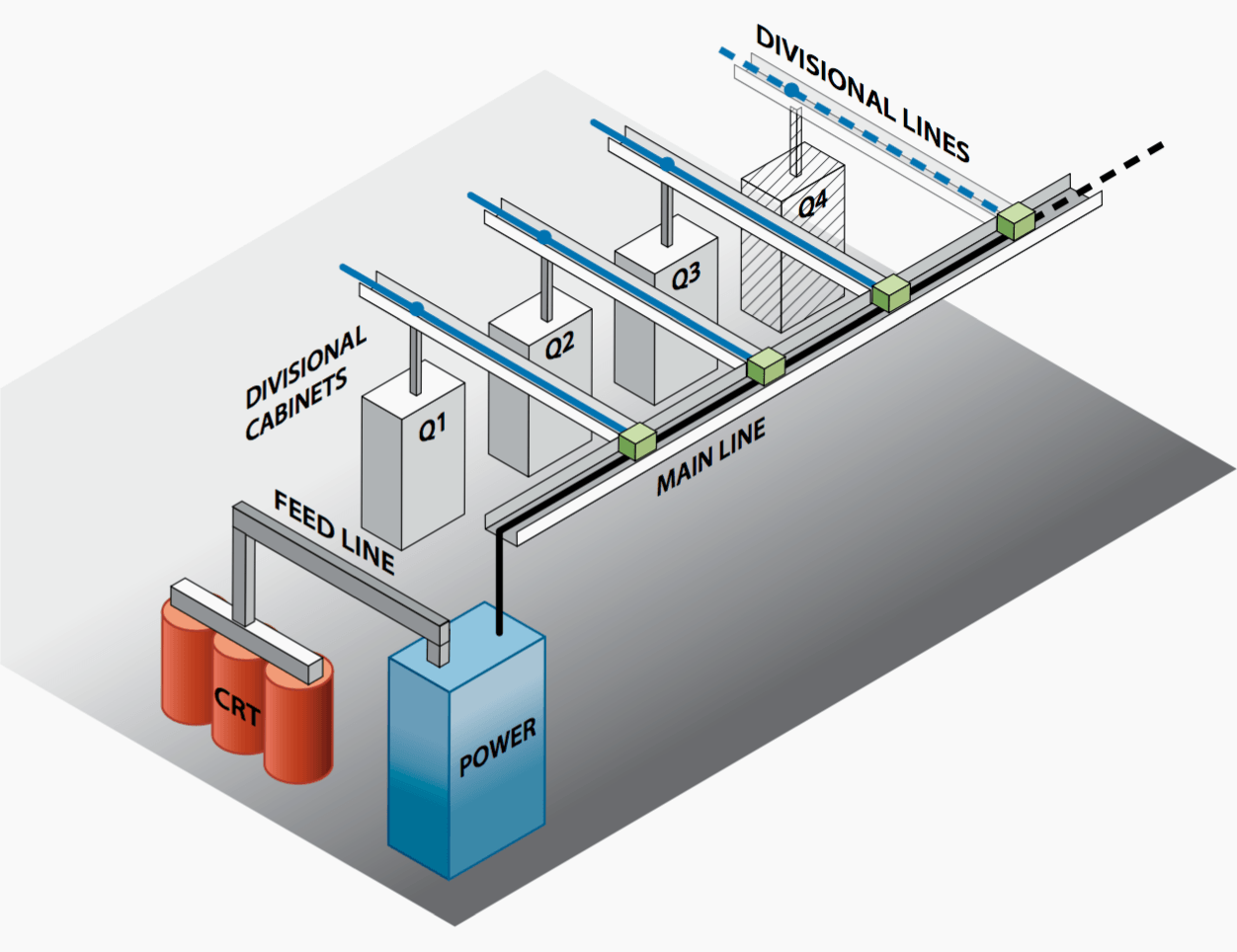
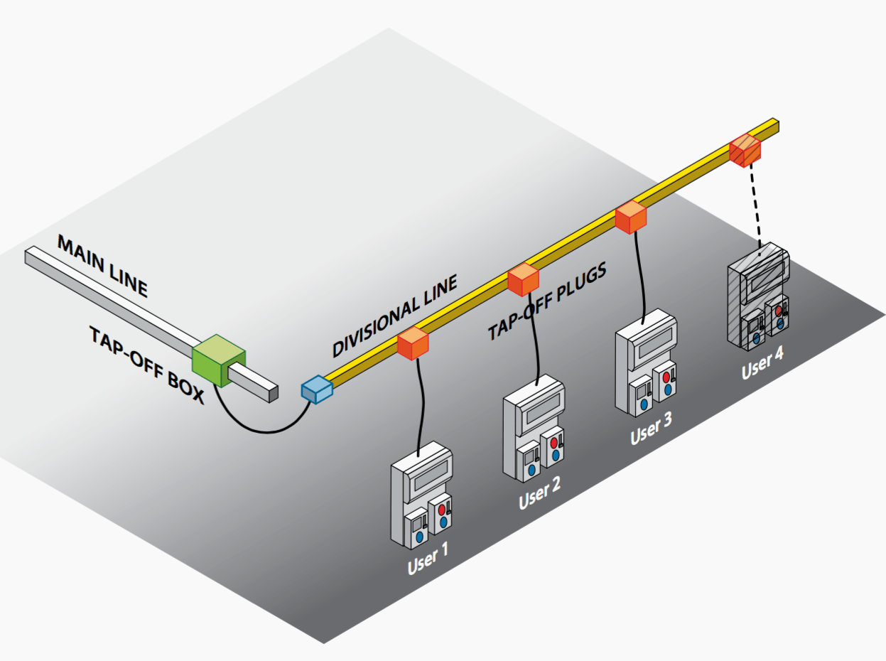
With the “prefabricated busbar system” solution, the busbars used as main lines are fitted with connection points. In this case, to power new lines, junction boxes simply have to be fitted directly onto the busbar. If required, these junction boxes will be equipped with protection or isolation devices.
Similar precautions will be taken at terminal circuit level to ensure maximum flexibility, should there be changes in the layout of workstations and/or an extension.
Go back to installation tips ↑
Reference // Transport and distribution inside an installation – The power book no. 13 by Legrand


thanks
thanks for the informations and it adds up our knowledge in busbars. Our design in one of our busbar was installed from ground and end it at the 6th floor. cable was install from load side of the tap off and terminated to an ACB for AHU at 11th floor. approximately 60 meters length of the cable from tap off to the ACB. My question is there any regulations or limitation on the length of cables from tap off unit to another main panel (ACB)?
Dear Sir,
Your web site is good enough to understand many concepts but I feel the things can be managed in order to understand same things but in a order not in a random manner. For example if want to learn a PLC programming I must be get data in a manner … Intro.. basic Concepts.. programming languages..devices for automation.. then a little higher level.. then more complicated examples.. then advanced programming.. then industrial tools and devices currently in use in the industry.. I mean it will be a tag form or in menu for learners…
I would like to ask you sir, as you are expert of LV design.. could you share the names of famous software in use for designing now a days for LV , HV, Bus Bar design…Power plant design ..Thanks
I am an electrician just learning AutoCAD and want to know more about basic programming autocad, autocad especially electricity.