
Setting into operation of automatic compensation banks
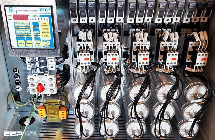
Circuit diagram of an automatic compensation bank is shown in Figure 1 below. The bank itself delivered by the manufacturer is entirely wired up and ready to connect. The main work for the electricians is to connect the bank with the selected power cables to the distribution plant. The provided fuses or load circuit breaker must comply with the specifications.
Before installing a new automatically controlled compensation bank the technical data have to be checked to see whether the bank complies with the requirements listed in the individual orders, such as:
- Is the rated voltage identical to or higher compared with the nominal voltage of the grid?
- Is the rated reactive power sufficient for the application, and even extendable if required?
- Does the admissible ambient temperature compare with the real one?
- If reactor protected, is the reactor rate identical to the ordered one?
- Does the integrated power factor controller fulfil the input data with reference to the external current transformer? Are free steps available for extension?
- Is the space for locating the bank sufficient, dry and not too close to heat-emitting devices?
- Is the location free of vibrations (if not, the bank is to be set on gum buffers)?
- Are the technical data of the compensation bank always visible?
Further, a cable with a cross-section of at least 2 × 2.5 mm2 is to be laid from the measuring current transformer to the power factor controller in the automatic compensation bank.
