
Estimated Study Time: 49 minutes
Transformer specification
Nothing is more crucial during the early phase of a transformer inquiry than a complete and explicit listing of all requirements that must be met from both the manufacturer’s and the user’s perspectives. The IEC standards include detailed requirements that affect the design and manufacture of transformers depending upon their rating, voltage and application.
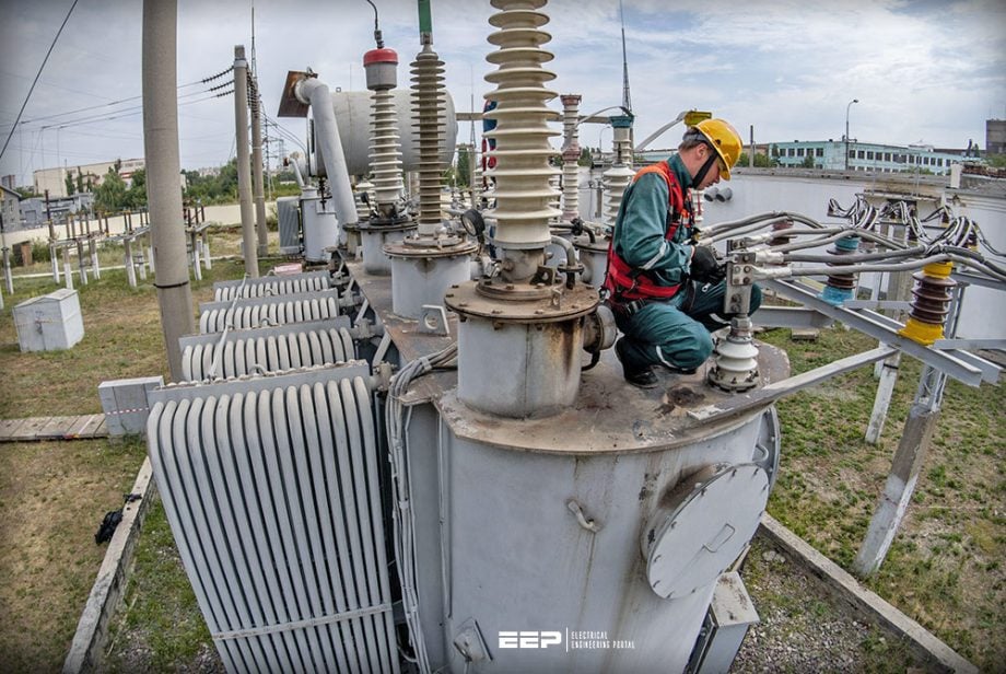 How to prepare an enquiry for a power transformer: Design and tendering tips
Often, however, there are other additional local or regional technical requirements that need to be included in a specification, as well as requirements which arise from the purchaser’s previous experience. Therefore, the purchaser should state any technical requirements different from or not contained in the IEC standards or other listed standards.
Any additional technical information that will assist a manufacturer to optimize the design and manufacture of the transformer should also be provided by the purchaser.
A technical specification has three most important objectives:
1st OBJECTIVE – To give the manufacturer, or tenderer, all the technical details he needs to implement his design and which will differ from unit to unit, such as rating, voltage ratio, cooling type, etc.
2nd OBJECTIVE – To inform the manufacturer or tenderer of the strategic significance of the transformer and the importance that should be given to dependability, maintainability, and long service life.
3rd OBJECTIVE – To give the tenderer, or manufacturer, information that will guarantee the transformer will satisfactorily interface with its aforementioned plant and equipment and that installation and commissioning will go smoothly and without undue delays.
The first two objectives must be accomplished by the inquiry paper for the manufacturer to be able to create his tender, and it is obvious that they will have a considerable impact on the transformer’s price. The third will have a lot of elements that will have little to no impact on total cost and that may be resolved during contract engineering.
It is important to remember that the purpose of a specification is not solely to describe what is wanted but also, to state what is not wanted. The latter often result from the purchasers’ previous experience.
Equally, the manufacturers’ experience can also complement the purchaser’s specification. Therefore the opportunity exists during the tender stage for exchanges of further information between the purchaser and the manufacturer by means of formalized design reviews and consultations.
- IEC/ISO standards
- Normal and Abnormal Operating Conditions:
- Design Requirements:
- Transformer Core
- Transformer Tank
- Insulating Fluid
- Bushings
- Secondary Wiring and Control Cabinets
- Fittings
- Tap Changers
- Monitoring
- Interchangeability
- Standardization
- Exclusions
1. IEC/ISO standards
Transformers should conform to the standards listed in the specification. Please see Table 1 for recommended list of standards. Where the purchaser has a distinct preference for either a core type or shell form transformer this must be clearly stated in the specification.
Table 1 – Recommended list of IEC/ISO standards
| IEC/ISO Standard | Description |
| IEC 61869 | Instrument transformers |
| IEC 61869-2 | Instrument transformers |
| IEC 60050 | International Electrotechnical Vocabulary |
| IEC 60050(421) | International Electrotechnical Vocabulary – Chapter 421: Power transformers and reactors |
| IEC 60060-1 | General definitions and test requirements |
| IEC 60060-2 | Measuring systems |
| IEC 60071-1 | Insulation coordination – Part 1: Definitions, principles and rules |
| IEC 60071-2 | Insulation coordination – Part 2: Application guide |
| IEC 60076-1 | Power transformers – Part 1: General |
| 1IEC 60076-2 | Power transformers – Part 2: Temperature Rise for liquid-immersed transformers |
| IEC 60076-3 | Power transformers – Part 3: Insulation levels, dielectric tests and external clearances in air |
| IEC 60076-4 | Power transformers – Part 4: Guide to the lightning impulse and switching impulse testing – Power transformers and reactors |
| IEC 60076-5 | Power transformers – Part 5: Ability to Withstand Short-circuits |
| IEC 60076-6 | Power transformers – Part 6: Reactors |
| IEC 60076-7 | Power transformers – Part 7: Loading guide for oil-immersed power transformers |
| IEC 60076-8 | Power transformers – Part 8: Application Guide |
| IEC 60076-10 | Power transformers – Part 10: Determination of sound levels |
| IEC 60076-18 | Power transformers – Part 18: Measurement of frequency response |
| IEC 60137 | Bushings for Alternating Voltages above 1000V |
| IEC 60214-1 | Tap-changers – Part 1: Performance requirements and test methods |
| IEC 60214-2 | Tap-changers – Part 2: Application Guide |
| IEC 60270 | High-voltage test techniques – Partial discharge measurements |
| IEC 60296 | Fluids for electrotechnical applications – Unused mineral insulating oils for transformers and switchgear |
| IEC 60422 | Mineral Insulating Oil in Electrical Equipment – Supervision and Maintenance Guide |
| IEC 60529 | Degrees of Protection provided by Enclosures (IP Code) |
| IEC 60567 | Oil-filled electrical equipment – Sampling of gases and analysis of free and dissolved gases (Guidance) |
| ISO 8501-1 | Preparation of steel substrates before application of paints and related products – visual assessment of surface cleanliness |
| ISO 9001 | Quality management systems – requirements |
| ISO 12944-2 | Paints and varnishes – corrosion protection of steel structure by protective paint systems – classification of environments |
| ISO 14001 | Environmental systems – requirements, with guidance for use |
| ISO 19011 | Guidelines for quality and/or environmental management systems auditing |
Go back to the Contents Table ↑
2. Normal and Abnormal Operating Conditions
The following should be specified:
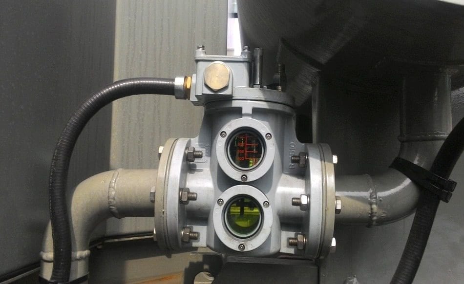
2.1 Gas and Oil Actuated Relays
Gas and oil actuated relays, used to indicate presence of accumulated gas or sudden oil movements, should not operate inadvertently when any combination of pumps start up and run, or in the event of loss or restoration of the auxiliary supply.
Figure 1 – Buchholz Relay
Go back to the Contents Table ↑
2.2 Overloads
It is only necessary to specify overload requirements in detail where they are in excess of what is listed in IEC standard 60076-7. It would be as well to state this directly. Where more onerous requirements are specified, the following information should be included as a minimum:
- Preload (and duration)
- Overload (and duration)
- Ambient temperature
- Maximum allowable temperatures during overload
- Method of test or verification
In case of partial loss of cooling equipment, similar considerations will apply. Note that restrictions may apply to the use of tap changers during overloads.
Suggested Reading – Where and how to find the root cause of a power transformer failure
Where and how to find the root cause of a power transformer failure (troubleshooting guide)
Go back to the Contents Table ↑
2.3 Geomagnetic Induced Current Effects
Solar activity can cause Geomagnetic Induced Currents (GIC) to flow in the earth and these currents can find their way onto the power system usually via the earthed neutral points of transformers. The occurrence of GIC’s in electrical grids is linked to position on the earths’ surface and to the orientation and length of overhead line circuits connected.
Higher latitudes are generally more affected, being closer to the magnetic poles. Purchasers should determine whether the transformer being specified will be located at a site which may be subjected to GIC events from time to time.
The temperature rise experienced in any object is depending on:
- Details of the design
- Constructional details
- Intensity of the GIC in duration and magnitude
- Loading condition of the transformer
- Heat transfer capacity of the affected structures
Purchasers should note that certain transformer types are more susceptible to GIC type events, including the use of five limb cores, single phase units and shell type transformers. Where GIC’s are a potential risk the purchaser may state this and any preference in transformer design for avoiding GIC effects.
Additionally the purchaser may specify the maximum magnitude of the GIC to be considered in the design and the time period that this current must be carried by the transformer.
Suggested Guide – Geomagnetic induced current as a severe threat to power systems
Geomagnetic induced current as a severe threat to power systems
Go back to the Contents Table ↑
3. Design Requirements
3.1 Flux density
The flux density in any part of the magnetic circuit including shunts should not attain a value that causes saturation. This should apply under the specified voltage, frequency and tap positions, including transitory effects of combined system voltage and frequency fluctuations. An adequate safety margin should be included.
The purchaser should state the over-excitation capability of continuous operation above rated voltage and at frequencies above and below rated frequency. A minimum acceptable V/Hz ratio could be specified for unloaded and fully loaded conditions.
Related electrical guides & articles


Edvard Csanyi
Hi, I'm an electrical engineer, programmer and founder of EEP - Electrical Engineering Portal. I worked twelve years at Schneider Electric in the position of technical support for low- and medium-voltage projects and the design of busbar trunking systems.I'm highly specialized in the design of LV/MV switchgear and low-voltage, high-power busbar trunking (<6300A) in substations, commercial buildings and industry facilities. I'm also a professional in AutoCAD programming.
Profile: Edvard Csanyi
