
Estimated Study Time: 21 minutes
The Art of Synchronizing Generator to Grid
Synchronizing the generator to the grid can be tricky if you don’t know what you’re doing. But let’s start from the beginning. A device that transforms mechanical power from a prime mover into AC electric power at a particular voltage and frequency is called a synchronous generator. The electrical frequency of this machine is locked in or synced with its mechanical rate of shaft rotation, which is why it is called synchronous.
The synchronous generator is utilized to generate the biggest share of electric power consumed globally. The internally generated voltage of this machine is contingent upon the rotational speed of the shaft and the magnitude of the field flux.
The phase voltage of the machine is affected by armature response in the generator, as well as by the internal resistance and reactance of the armature windings, resulting in a difference from the internally generated voltage. The terminal voltage of the generator will either match the phase voltage or be proportional to it by √3, based upon whether the machine is delta or star-connected.
The operation of a synchronous generator inside a real power system is contingent upon its restrictions. When a generator works independently, the actual and reactive power requirements can be determined by the connected load, while the governor set points and field current control the frequency and terminal voltage, respectively.
When the generator is coupled to an infinite bus, its frequency and voltage remain constant; thus, the governor set points and field current control the real and reactive power output from the generator.
The maximum permissible heating in the armature windings determines the maximum kilovolt-amperes allowable from the machine, whereas the maximum permissible heating in the field windings establishes the maximum size of EA.
The combined maximum sizes of EA and IA determine the generator’s rated power factor.
Conditions for Synchronization
In order to synchronize a generator with the grid, it is necessary to fulfill the following four conditions:
- Phase Sequence
- Voltage Magnitude
- Frequency
- Phase Angle

1. Phase Sequence
The phase sequence (or phase rotation) of the three phases of the generator must be the same as the phase sequence of the three phases of the electrical system (Grid). The only time that the phase sequence could be wrong is at initial installation or after maintenance. There are two possible problem sources.
The generator or transformer power leads could actually be interchanged during maintenance orthe potential transformer leads could be interchanged during maintenance.
2. Voltage Magnitude
The magnitude of the sinusoidal voltage produced by the generator must be equal to the magnitude of the sinusoidal voltage of the grid. If all other conditions are met but the two voltages are not the same, that is there is a voltage differential, closing of the AC generator output breaker will cause a potentially large MVAR flow.
Recall that before a generator is synchronized to the grid, there is no current flow, no armature reaction and therefore the internal voltage of the generator is the same as the terminal voltage of the generator.
If the generator voltage is less than the grid voltage, this means that the internal voltage of the generator is lower than the grid voltage. When it is connected to the grid the generator will be under-excited and it will absorb MVAR.
3. Frequency
The frequency of the sinusoidal voltage produced by the generator must be equal to the frequency of the sinusoidal voltage produced by the grid. In Figure 2 below the generator is slower than the grid.
Figure 2 – Generator Slower than Grid

The synchroscope would be rotating rapidly counter clockwise. If the generator breaker were to be accidentally closed, the generator would be out of step with the external electrical system. It would behave like motor and the grid would try to bring it up to speed.
In doing so, the rotor and stator would be slipping poles and damage (possibly destroy) the generator as described previously. The same problem would occur if the generator were faster than the grid.
The grid would try to slow it down, again resulting in slipping of poles.
Figure 3 – Generator at Same Speed as Grid but not in Phase

Figure 3 shows the condition where the generator and grid have matching speed. The high points and zero crossings of the sinusoidal voltages occur at the same rate of speed.
However, if you notice in 2 with the grid and a phase angle exists between them. This would appear as a non-rotating synchroscope (both generator and grid at same frequency), where the pointer would appear stuck at about 9:00 o’clock (generator lagging grid).
If the generator breaker were to be closed at this time, the grid would pull the generator into step.
Hence the generator must be brought to a point where the grid voltage waveform exactly matches what it is producing.
4. Phase Angle
As previously mentioned, the phase angle between the voltage produced by the generator and the voltage produced by the grid must be zero. The phase angle (0 to 360°) can be readily observed by comparing the simultaneous occurrence of the peaks or zero crossings of the sinusoidal waveforms.
If the generator breaker is closed when they match exactly, the connection will appear smooth and seamless.
The worst case occurs if the generator is exactly out-of phase, with a phase angle of 180° and the synchroscope pointing at 6:00 o’clock.
Figure 4 – Generator in Phase with Grid

Synchronisation of Generators to a Busbar (VIDEO)
Parallel operation of AC generators
In modern grids, an isolated synchronous generator independently supplying its own load without dependence on other generators is very uncommon. This condition occurs in only a limited number of specialized applications, such as emergency generators. In typical generator installations, multiple generators operate parallel to meet the power demands of the loads.
An extreme instance of this scenario is the U.S. power grid, when thousands of generators collectively distribute the system’s load. What is the rationale for operating synchronous generators in parallel?
There are numerous significant advantages to this operation:
Advantage #1 – Supplying a bigger load
Multiple generators may supply a greater load than a single machine alone.
Advantage #2 – More Generators, the Better
The presence of many generators enhances the reliability of the power system, as the failure of any single generator does not result in a complete power loss to the load.
Advantage #3 – More Generators in Parallel
The operation of multiple generators in parallel permits the removal of one or more units for shutdown and preventive maintenance.
Figure 5 – A generator being paralleled with a running power system
Advantage #4 – More Smaller Generators in Parallel
If a single generator is utilized and it operates below near full capacity, it will show relative inefficiency. By utilizing multiple smaller machines in parallel, it is feasible to operate merely a subset of them.
The machines that are operating, are near full capacity, hence enhancing efficiency.
Paralleling AC Generators
The Prerequisites Required for Paralleling
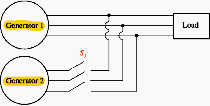
Before examining the behavior of synchronous generators running in parallel, let’s examine the prerequisites for paralleling AC generators. Figure 5 depicts a synchronous generator G supplying electricity to a load, along with another generator G, which is about to be paralleled with G by shutting the switch S1.
Before the switch is closed and the two generators are connected, what requirements need to be fulfilled?
The following paralleling requirements must be fulfilled in order to accomplish this match:
- The two generators’ rms line voltages need to be the same.
- The phase sequence of the two generators must match.
- The two a phases’ phase angles have to match.
- The new generator, also known as the oncoming generator, needs to have a frequency that is marginally higher than the operating system’s frequency.
We need to explain these paralleling circumstances. The first Condition is clear: two sets of voltages must, of course, have the same rms magnitude of voltage in order to be identical. Condition 3 is explained by the fact that if the magnitudes and angles of the voltage in phases a and a’ are the same, the voltage will always be exactly the same.
Just switching the connections on any two of the three phases on one of the machines fixes a phase sequence issue. There will be significant power transients until the generators stabilize at a common frequency if their frequencies are not nearly identical when coupled. Although they cannot be precisely equal, the frequencies of the two devices must be quite close to one another.
They must be slightly different in order for the incoming machine’s phase angles to gradually alter in relation to the operating system’s phase angles. When the systems are precisely in phase, switch S can be closed and the angles between the voltages can be seen.
The General Procedure for Paralleling Generators (Old School)
Assume that the operating system depicted in Figures 6 and 7 is to be connected to generator G. To complete the paralleling, the actions that follow need to be performed. The field current of the oncoming generator should first be regulated with voltmeters until its terminal voltage matches the line voltage of the operational system.
The second step is to compare the phase sequence of the running system with that of the oncoming generator.
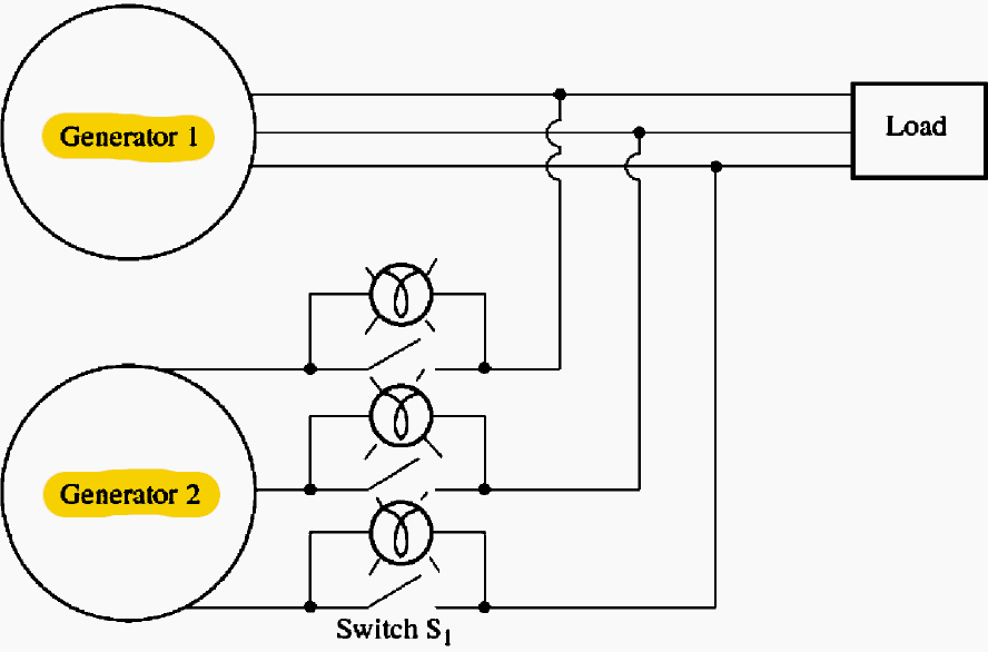
As illustrated in Figure 7, this method involves stretched three light bulbs across the open terminals of the switch that connects the generator to the system. The light bulbs first become bright (big phase difference) and subsequently dim (small phase difference) as the two systems’ phases shift.
The systems have the same phase sequence when all three bulbs turn on and off simultaneously.
Figure 6 – Two possible phase sequences of a three-phase system
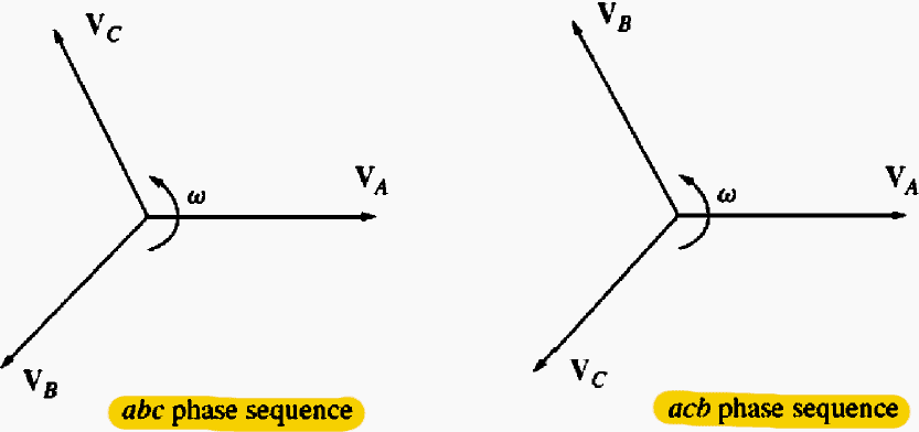
The systems have the opposite phase sequence if the bulbs light up one after the other, thus one of the sequences needs to be switched.
The oncoming generator’s frequency is then set to be slightly higher than the operating system’s frequency. This is accomplished by first monitoring a frequency meter until the frequencies are near to one another, and then by looking for variations in the systems’ phases.
In order for the oncoming generator to supply electricity as a generator rather than consume it like a motor would, it is set to a slightly higher frequency when it is connected.
Observing the three light bulbs mentioned above in relation to the phase sequence discussion is an easy old-school method. The systems are in phase when all three light bulbs are out and there is no voltage differential across them.
However, although this straightforward plan is effective, it is not very precise.
Figure 7 – The three-light-bulb method for checking phase sequence
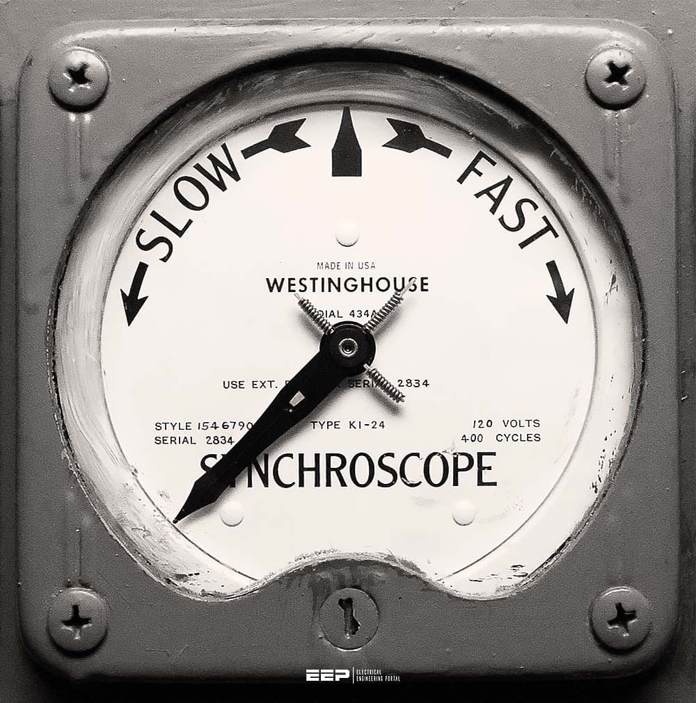
Using a synchroscope is a superior method. A meter that gauges the phase angle difference between the two systems’ phases is called a synchro-scope. Figure 8 shows the face of a synchroscope. With 0 (indicating in phase) at the top and 180° at the bottom, the dial displays the phase difference between the two a phases.
The phase angle on the meter varies gradually because the frequencies of the two systems differ slightly. The phase angle advances and the synchroscope needle revolves clockwise if the oncoming generator or system is faster than the operating system (the ideal scenario).
However, for smaller generators, the operator performs the previously mentioned paralleling stages by hand.
Figure 8 – Synchroscope is used to connect two different sources
Recommended Course
Learn How to Operate and Analyze Interlocking Schemes for Substation & Gas Insulated Switchgear (GIS)

Related electrical guides & articles


Edvard Csanyi
Hi, I'm an electrical engineer, programmer and founder of EEP - Electrical Engineering Portal. I worked twelve years at Schneider Electric in the position of technical support for low- and medium-voltage projects and the design of busbar trunking systems.I'm highly specialized in the design of LV/MV switchgear and low-voltage, high-power busbar trunking (<6300A) in substations, commercial buildings and industry facilities. I'm also a professional in AutoCAD programming.
Profile: Edvard Csanyi

Hi, I am constructing a 6 MW Small Hydro Power Project. Want to evacuate power through existing line which is running near the project. The line connects to the grid. I want to evacuate by tapping on the existing line. Any suggesion
Totally possible if deliered to grid at same voltage and sync wave phase
well, assuming that the synchronous machine is connected to and running on the grid (synchronized), what needs to be changed in order to cause the machine to draw power from the grid (to act as a load) or to deliver power to the grid (to act like a source)?
Slight increase or decrease in speed will cause a change in current flow
Sand me synchronize system DWG
hello i am currently doing a university course in electrical engineering i was wondering if you anyone could give me information on why the frequency needs to be synchronised first and then followed by the voltage probably very basic answer just cant find it. thanks for any help
The angular velocity will accelerate/decelerate if frequency is not synchronised first, thus preventing, voltage synchronism.
first we adjust the frequency by increasing/decreasing engine speed.
. by adjusting the frequency also the voltage will be affected
E or V (generator)=N(stator)* Magnatic Field of the Rotot * w
as w=2*pi * f
so now f is adjusted already and it is fixed after that we will adjust V(generator)
and that will be done by AVR or manually by VR
adjusting V(generator) is actually done by adjusting the current of the (stator excitor) which would change the magnatic field of the main rotor and eventually the V(generator) would be changed(adjusted).
if you adjust the voltage first then adjusting the frequency in this case will lead the V(generator) to be changed as per the equation mentioned before
hi there i am currently doing a university course in electrical engineering i was wondering if you anyone could give me information on why the frequency needs to be synchronised first and then followed by the voltage probably very basic answer just cant find it. thanks for any help
How to synchronize 33KV star with 33kv delta
When I question the synchronization of generator 1 with generator 2, generator 2 is disconnected at 500 kW load When I question the synchronization of generator 1 with generator 2, generator 2 is disconnected at 500 kW load with trip cutter separated
very helpful
Pls. how do i solve this problem. i run a drilling rig with 3 Generators, whenever i tried to synchronized 2 gen the power percentage increased to 65% without load, please what would do resolve this problem.
thanks
Respected sir
My question is related to inter connected power system please tell me how to decide after synchronizing of generator with grid how much power will flow from generator.
Assume that gride voltage is 1P.U at ange 0 degree.
And my second question is how to flow power from generator as our requirement means if i want to flow power from my synchronized generator only 5MW so which setting is to be changed
Assume that gride voltage is 1P.U at ange 0 degree also i have one master generator unit.
Hello
How this led meter is working with this generator synchronization please tell
HELLO
what is use of this LED rotating in this panel
That LED will indicate the phase angle difference between the voltage generated by DG and grid voltage. When speed of governor is increase the frequency of generated voltage also increases in same proportion. Synchroscope is LED is showing how much difference is their in the frequency of dg and grid voltage. If LED is in too slow region then we need to raise governor speed and vice versa.
The guy first raises speed manually and then put in auto mode which makes DG frequency same as grid frequency by slowing down governor.
I hope you are cleared.
Please the generator voltage,the frequency at the speed of 100 percent are okey before synchronization. the problem is upon turning on the synchro switch it will grab the load from the grid
Synchronization with Grid explained in most simple manner with clarity. Thanks for sharing
I want to know If three phase (coming from generator output through step down transformer) connected to AVR, gets interchanged by any two phase, will it give the phase angle fault at the time of synchronisation of generator with Main busbar kindly guide me.
i have two , 1500 KVA generators with synchronizing , panel , sometimes ,synchronizing take more than 3 minutes , which is not accepted by client. what is the standard time , why it so long , why this problem happenand how to solve.
You can reduce the delay time on the ATS module. But the delay time is good for balancing of the load and parameters before closing the busbar or circuit breaker
Group of 4 gensets of 1010 kva cummins set with stamford alternator is running in parallel and load is injection moulding unit the load on Dg sets is around 40 % due to load varying in injection process when the plant is running every 3 min there will be a load of 1.3 MVA on the sets, during the process if we want to reverse Synch with the grid what type of issues we might face.
If a generator is supplying a load which is equal to 90% of the generator’s rated out put, would the synchroniczation procedure to the grid be the same?
The generator’s share of the load at synchronisation is zero, other generators are supplying the load at that time, that is why the frequency of the grid is 60 Hz. After synchronisation you can load the generator to the 90% of rated output that you mention. The other generators on the system would have their outputs reduced accordingly. So to answer your question, it doesn’t matter what the generator’s output will be, at the moment of synchronising the output is zero.
What is frequency tolerance limits for system synchronization condition for two different power sources (Generator and bus bar)
Hello, I would like to have information as how to generate the grid frequency using the synchronous generator or DFIG or PMSG in the wind turbines. What are the converter parameters we need, to get the frequency as 50Hz and the voltage as 690 volts at the grid side? As my academic project is based on this issue. I am looking forward for your help. Please help me on this issue
I have 40kva And 60kva Hw can I sychoronize The both of Generator
We have two generator of 15MW having 11KV voltage which runs in parallel.when load requirment exceeds 30MW we have to syncronised generators with grid which is 132/11KV.When grid runs in parallel with generator the average powerfactor of grid is poor due to which we have to pay baby penalty to EB.But when load puts on grid indipentantly running as well as average powerfactor is good.Please guide me why such type of condition occur and also how to avoid poor powerfactor during synchronised condition.
You can have OLTC to improve the power factor. You can also install capacitor banks to improve the condition.
Dear Edvard,
Greetings,
Please tell the advantanges and disadvantages of having GCB at STG, in order to avoid direct synchronizing with HV breaker.
thank you for this page …. but i not understand 4. Phase Angle part
I would like to synchronise 440/220 volts 3 phase 4 wire generator with grid transformer of 11000/433V delta wye. How do I do that?
thanks for providing a real good and easy concept of synchronization. Well done, Keep it up. A good service to the electrical engineering community.
My problem is that have one generator run in meanwhile the two are connected to synchronizing panel (both Gen has 1000kw rating each) so when on the second Gen and synchronize the the total load move the new gen just on please what is the Problem
Wow! this is great!This is good write up,its very helpful.God bless….
Thank you for shearing your wonderful knowleadge.
For emergency generation purposes where your site is normally powered by the Grid the benefit of running in this fashion is that you ensure that when running in parallel, if the grid supply is lost then you ensure 100% of your site load can be comfortably transfered to the emergency generator. I have direct experience of manually closing generator circuit breakers to the grid supply, you soon learn to have all the parameters as close to the grid as possible. The main problem is getting the generator speed (frequency) controlled so that the frequency is synchronised as close to the grid as possible.
i need to synchronize my unit with grid. but last time we done it but it make fluctuation in voltage and some cards are buringi…i dont know why… any one can aswer for my querry…
I want to synchronize the Gas Turibine Generator with the Grid at 11kV Level. The Generator is generating Voltage at 11kV with Dyn11, 11/ 11kV Generator Isolation Transformer. We are receiving Grid Power through Yy0, 132/11kV Transformer. Can they be made parallel? Can Voltages be at the same Phase Angle.
I need how to connect and synchronize the mains with a generator
I need to couple with synchroscope
Sir my question is practically we keep the generator voltage and frequency slightly higher than the grid voltage. Why is this done?
I work at a powerhouse and we have 6 30MW hydro generators. We have 3 to a bus. last week the CO2 was set off by our 87G Relay on unit 4. Everything tested great. Yesterday the same thing happend to a different unit on the same bus. the operator on duty said as sood as he put the sycronizor in auto it closed the breaker. The sycn. was at 3 o’clock and it tripped the 87G. these 2 units are on the same bus. Since the first trip on unit #4 we have run unit #5 several times. Any thoughts on whats going on here.
Did you check with the synchronizer? is it OK? do check for abnormalities in the bus during switching. you might come to a conclusion.
How we can connect two generator one is150kva and other 180kva gen .when load increase on 150kva then 180kva will start .180kva is stand by.
Thanks for this article. However, there is no discussion on how to achieve same frequency, voltage and phase. The discussion on this will be helpful
My experience is limited to marine installations but the operating principles are the same.
The frequency of the incoming generator is regulated by varying the speed of the prime mover. The governor should handle that.
For the voltage, that is regulated by the AVR and it does this by varying the rotor field excitation on the generator.
Just as with the frequencies, for the voltage phase angles, a synchroscope or synchronising lamps will be the indicator as to when the voltages are in phase.
For the phase sequences, both the generator and grid busbars are checked using the same phase sequence meter. As mentioned by Edvard, the terminals can be interchanged if the phase sequence isn’t the same.
My explanation isn’t that detailed by I hope it helps.
Phase angel is the angel difference between the generator voltage and the grid voltage. While phase sequence means that the three phases of the generator must match with the same phases on the grid.
For example: A, B, and C are the three phases of the generator. Then to have the same phase sequence with the grid connect them to their match on the grid A to A etc…
Note down that u dont need to confirm this condition everytime u synchronyze the gen. with the grid. Because the gen. Is connected permenantly.
When paralleling the Generator to Grid, What % of variation in both the voltages are allowed & what is the criteria for it?
there is something that’s i want to ask you phase angle and phase sequence is it same function .. thats we done during synchronizing ..
Very neat, very helpful.
I have not come across any source e explaining the Synchronization concept this simple and they say “simplicity is the ultimate sophistication”
Great work!
many thanks you are a real kind man; you help many many people around world
many thanks
very helpful, i must say, never seen such a useful and efficient portal
Good article. It would be desirable to improve the PDF generator in Spanish to save it and print it, is failing