
Power availability and reliability
Power availability and reliability is a persistent problem and no matter the industry, or type of facility you run, downtime presents a costly risk to your operations and bottom line. Detecting electrical system vulnerabilities to prevent potential issues while planning quick, effective solutions when problems arise is key to making your operation more resilient and reliable.
 Learn how to prevent unplanned downtime and keep critical operations up and running
Power availability and reliability remain major and persistent problems. No matter the industry or type of facility, downtime presents a costly risk to business continuity. Identifying electrical system vulnerabilities in order to prevent potential issues, and planning quick, effective resolutions when problems do occur are key steps to help ensure your operation is as resilient and efficient as possible.
Today’s technology and automation dependent commercial and industrial (C&I) companies need reliable power to sustain daily operations. But according to the World Bank, Quality of Electricity Supply, in many developed countries, reliable power has remained static or decreased.
In addition to improved safety, power availability is likely every electricity consumer’s most basic concern. Even though International Electrotechnical Commission (IEC) standards have primarily focused on safety, electrical power availability and reliability is a major concern.
Key steps to maximize power system performance
Due to electrical infrastructure becoming more complex, the typical operation contains many hidden risks to dependable power availability, but by focusing on four key areas, power system availability and reliability can be maximized.
- Digital and Power Systems Reference Designs
- Selectivity to enhance uptime
- Electrical Asset Management
- Fault Localization, Root Cause, and Recovery
- Conclusion
1. Digital and Power Systems Reference Designs
Organizations need a robust, reliable power infrastructure to help ensure operational continuity and safety. Designing electrical distribution architecture correctly is critical to how an entire system performs throughout its lifecycle (see Figure 1), especially in the face of higher demand and increasing technical complexity.
This involves three main steps, see Figure 1:
- Selecting distribution architecture fundamentals
- Choosing the system architecture details
- Equipment selection
Figure 1 – Flow diagram for choosing the electrical distribution architecture
Go back to the Contents Table ↑
1.1 Selecting distribution architecture fundamentals
This includes classifying all the characteristics and requirements of the installation and how each element will impact the connection to the upstream network. Several distribution schematic-diagram solutions may be produced, any of which can be used as the starting point for the single-line diagram.
There are two stages to selecting an electrical architecture. The first stage is generally dedicated to the selection of the mode of connection of the installation to the utility network, and the choice of the internal MV distribution including:
- The definition of the number of MV/LV substations,
- The definition of the number of MV/LV transformers,
- The definition of the MV backup generator when needed.
The second stage deals with the principle of supply of the LV consumers.
Factors relevant to connecting an installation to the utility network (see Table 1, Figure 2 and 3) include the following:
Connecting a LV network for small and medium size installations that requires less than 400 kVA. Defining the limit is always the responsibility of the local utility managing the LV network. For connections to MV networks above 400kVA, using either LV or MV metering. LV metering is generally authorized for installation including a single MV/LV transformer not exceeding the rated power limit fixed by the utility, generally around 1250 kVA.
The possible connections to a MV utility network include the following:
- MV single-line service
- MV ring-main service
- MV duplicate supply service, including two load break switches equipped with an automatic change over.
- MV dual supply service that provide two independent connections to the utility and two bus bars connected with a bus tie, equipped with an automatic change over.
Table 1 – Comparison of the modes of connection
| Characteristic to consider | Configuration | ||||
| Low Voltage | Medium Voltage | ||||
| Single-line | Ring-main | Duplicate supply | Dual supply | ||
| Activity | Any | Any | Any | High tech, sensitive office, healthcare | Very sensitive installations |
| Site topology | Single building | Single building | Single or several buildings | Single or several buildings | Single or several buildings |
| Service reliability | Minimal | Minimal | Standard | Enhanced | Very high |
| Power demand | < 400 kVA | ≤ 1250kVA | Any | Any | Any |
| Other connection constraints | Any | Isolated site | Low-density urban area | High-density urban area | Dedicated measures taken by the utility |
Go back to the Contents Table ↑
1.2 Choosing the System Architecture Details
This step requires the electrical installation to be defined in greater detail and is a product of the requirements defined in step one, as well as satisfying any additional criteria related to the installation’s implementation and operation.
Any unsatisfied step one criteria should be resolved at this point and upon completion, a detailed single-line diagram will be produced.
Figure 2 – MV connection with LV metering
Figure 3 – MV connection with MV metering
Go back to the Contents Table ↑
1.3 Equipment selection
Specifying the appropriate equipment for optimal network performance is carried out in this stage, and is the result of the architecture chosen. Options are made from manufacturer catalogues to adequately meet relevant criteria.
Schneider Electric provides a free electrical installation wiki to guide any new or renovated electrical installation.
Harmonize with current standards and requirements such as IEC 60947-1, IEC 60947-2, IEC 60364, IEC 60364-5-56, and IEC 62586.
Benefits include:
- Significantly reduced installation time, effort, and technical expertise required by installers.
- Superior operational performance related to power quality and availability.
- Full lifecycle needs to be accommodated, including end-of-life considerations.
Go back to the Contents Table ↑
2. Selectivity – Coordination between Circuit Breakers
In an installation with proper selectivity, only the circuit breaker protecting the overloaded/faulted part of the electrical network will trip, limiting a service interruption to the circuit experiencing the problem rather than the entire system. The IEC 60364 series is mandatory for installations supplying safety services (IEC 60364-5-56 2009 560.7.4).
Selectivity may also be required by local regulations or for some special applications like healthcare facilities, marine, and high-rise buildings and is highly recommended for crucial applications like data centers, infrastructure, and critical processes.
Innovative software and digital tools help you optimize your installation design, calculate and size up your electrical components, and select combinations of circuit breakers that provide total selective coordination or optimized selectivity with cascading.
Figure 4 – Circuit breaker selectivity
Design and selection of equipment for LV electrical installations are required to consider and check the behavior of all devices on the current path in a fault situation. High short-circuit current can damage equipment by electrodynamical and thermal effects. Each device can individually withstand the worst effects, but it may require significant oversizing and, on occasion, may be impossible.
Schneider Electric provides “co-ordination” performances for two or three LV devices in the following cases:
Case #1 – Coordination related to continuity of supply and/or proper functioning
- Selectivity (also called discrimination)
- Selectivity enhanced by cascading
- Motor starter coordination type 2
- Circuit breaker and LV/LV transformers
Case #2 – Coordination related to safety
- Cascading (also called group short-circuit protection, or back up protection)
- Motor starter coordination type 1
- Coordination between switch-disconnector and circuit breaker or fuses
- Coordination between circuit breaker and bus-bar trunking (busway) system
Suggested guide – Proper selection and overcurrent coordination of LV/MV protective devices
Proper selection and overcurrent coordination of LV/MV protective devices
Go back to the Contents Table ↑
2.1 Principles of Selectivity (Discrimination)
Selectivity is achieved by overcurrent and earth fault protective devices if a fault condition, occurring at any point in the installation, is cleared by the protective device located immediately upstream of the fault, while all other protective devices remain unaffected. Selectivity is required for installation supplying critical loads where one fault on one circuit does not cause the interruption of the supply of other circuits.
In the IEC 60364 series it is mandatory for installations supplying safety services (IEC 60364-5-56 2009 560.7.4).
From an installation point of view: selectivity is achieved when the maximum short-circuit current at a point of installation is below the selectivity limit of the circuit breakers supplying this point of installation. Selectivity must be checked for all electric circuits supplied by one source and for all types of fault:
- Overload
- Short-circuit
- Earth fault
Suggested study – Circuit breaker selections for low voltage installation (with discrimination)
Circuit breaker selections for low voltage installation (with discrimination)
When a system can be supplied by different sources (grid or generator set, for instance) selectivity shall be checked in both cases. According to the IEC 60364-5-53:535 2019 standard, the selectivity between two circuit breakers can be:
- Partial: up to a specified value according to circuit breakers characteristics (Is)
- Full: up to the maximum prospective short-circuit (Isc_max) current on the load side of the downstream circuit breaker
- Total: up to the breaking capacity (Icu or Icn) of the downstream circuit breaker
- Enhanced: up to a value higher than the breaking capacity of the downstream circuit breaker when cascading is applied
In an electrical installation, selectivity performance depends on the two circuit breakers characteristics and the installation’s maximum short-circuit current on the load side.
The table below summarizes these different situations:
Table 2 – Selectivity in a given installation according to circuit breakers selectivity performance without or with cascading (or backup or combined short-circuit protection)
| Characteristic to consider | Short-circuit current on the load side versus the selectivity limit Is of the two circuit breakers | Selectivity consequence for the electrical installation | |
| Without cascading | Partial | Is ≤ Isc_max < Icu (or Icn) | “Partial” (Example 1a) |
| Isc_max < Is < Icu (or Icn) | “Full” (Example 1b) | ||
| With cascading | Total | Isc_max ≤ Is = Icu (or Icn) | “Total” (Example 2) |
| Partial | Is < Icu < Isc_max | Partial (up to Icu but < Isc max) | |
| Total | Is = Icu < Isc_max | Enhanced selectivity | |
| Enhanced | Icu < Isc_max ≤ Is_enhanced | (up to Is_enhanced) (Example 3) |
Where:
- Icu is breaking capacity of circuit breaker according to IEC/EN 60947 series
- Icn is breaking capacity of circuit breaker according to IEC/EN 60898 or IEC/EN 61009 series
Click the links below for more selectivity information and resources:
- Guide: Selectivity, Cascading, and Coordination
- Guide: Electrical Installation Guide
- Blog: Optimizing installation costs with circuit breaker cascading
- Blog: Circuit breaker selectivity for power availability
- Calculation Tool: EcoStruxure Power Design
Go back to the Contents Table ↑
3. Electrical Asset Management
You need to monitor and visualize your critical electrical assets to maintain them properly, increase their reliability, cost-efficiency, and enhance asset lifecycle management. Effective electrical asset management can be divided into two functions, operational intelligence, and preventative maintenance.
3.1 Operational Intelligence
By not taking advantage of the latest advances in power distribution connectivity and intelligence means you could be working blind, unaware of many hidden risks and opportunities already within your facilities. Maximizing power availability and reliability takes more than a resilient electrical system design. It also requires an intelligent, digital infrastructure embedded into the electrical equipment connected to specialized power management software.
Only then will you have the actionable insights needed to operate reliably and avoid unplanned power disruptions.
All-in-one solutions and services across various applications and technologies are readily available to reduce maintenance costs and improve productivity.
Figure 5 – Latest advances in power distribution connectivity and intelligence
Go back to the Contents Table ↑
3.2 Preventative Maintenance
Performing maintenance before things break minimizes the cost of owning and operating an electrical system. Repairs are often costly, but the price of business continuity can be insurmountable. Digital asset tracking can help facility maintenance teams improve maintenance effectiveness and efficiency over traditional methods, producing large amounts of cumbersome, complex, and time-consuming manual documentation.
Ensure business continuity and prevent downtime caused by prolonged equipment failure with a solution that monitors your equipment condition 24/7 and alerts you to issues before they occur.
Click the links below for more electrical asset management information and resources:
- White Paper: Mitigate risk using power management systems
- Blog: Preventive Maintenance Minimizes Electrical Facility Problems and Costs
- White Paper: How Predictive Maintenance of Circuit Breakers Boosts Reliability While Cutting Costs
- Demo: EcoStruxure Power Operation
Suggested reading – Testing specifications for preventive maintenance of electrical equipment
Testing specifications for preventive maintenance of electrical equipment
Go back to the Contents Table ↑
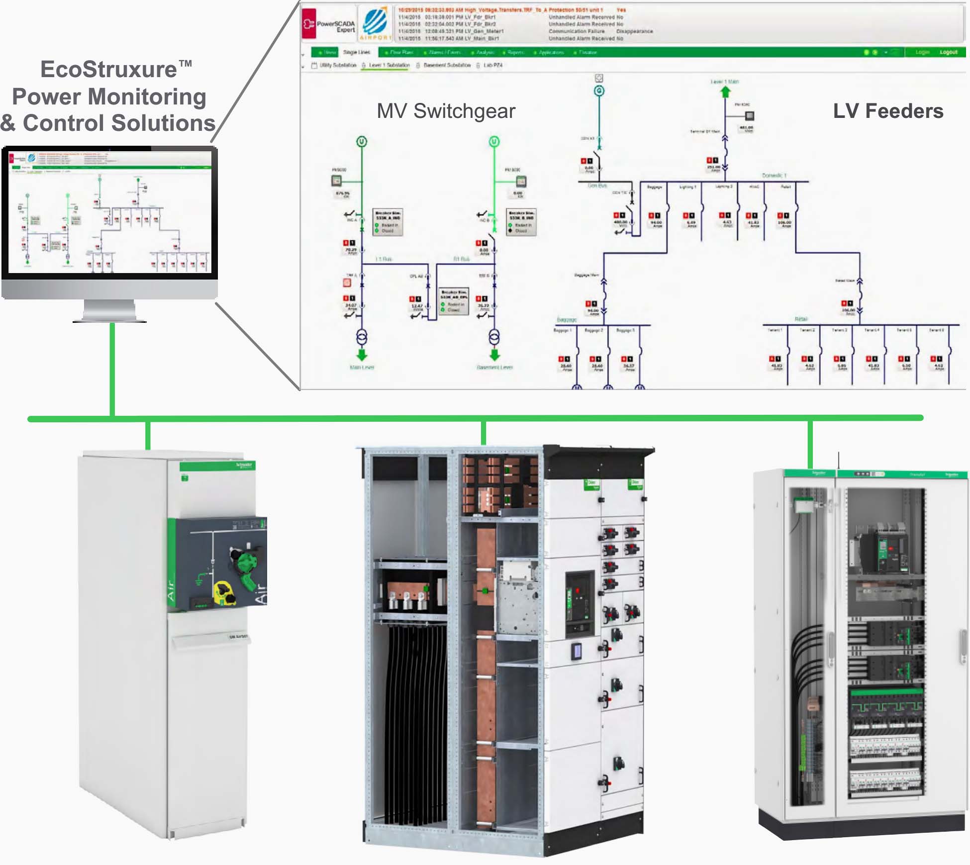
3.3 Electrical system monitoring and alarming
Help prevent downtime, increase electrical system reliability, and better protect assets with self-healing medium voltage (MV) loop architectures, and by connecting MV relays, low voltage (LV) breakers, thermal sensors, and power meters to power monitoring and control software to:
- Isolate faults with relay automation and breaker coordination.
- Preserve critical loads by automatically transferring to alternate power sources and by shedding non-critical loads.
- Restore power more quickly and securely using electrical diagnostic information and remote control of breakers.
Get real-time visibility, automation, and control of your entire electrical infrastructure from MV to LV to final distribution to every load.
Figure 6 – Electrical system monitoring and alarming
Go back to the Contents Table ↑
4. Fault Localization, Root Cause, and Recovery
Detecting and locating electrical installation faults is essential to the reliable, safe, and efficient electrical installation operation in virtually every industry and organization. Yet, grid power reliability is not improving, and more power electronics mean more harmonic pollution in electrical networks, causing a myriad of operational failures leading to more unplanned downtime.
Even with the most resilient electrical system designs – power disturbances and interruptions will happen.
Quick recovery solutions that can help include:
- Comprehensive selectivity for precise fault isolation
- Insulation monitoring and fault location
- Disturbance direction detection and power event analysis
Go back to the Contents Table ↑
4.1 Power event analysis
Help prevent downtime and increase electrical system and asset reliability through the use of specialized power event diagnostic tools. Use disturbance direction detection to determine the root cause of problems so you can make faster decisions with confidence and recover from faults more quickly.
Suggested Video – Ecostruxure Power Energy Usage Analysis
4.2 Fast outage recovery
At a workstation, sophisticated software tools allow for advanced power forensics, helping to speed up the diagnosis of power system incidents. High-accuracy time-stamping of
events provided by onboard smart devices – e.g., distributed meters, relays, data loggers, etc. – enable a visual timeline showing related events, waveforms, and trends to automatically be created. Custom filters can be used to show only what is most relevant.
Additionally, a patented diagnostic capability from Schneider Electric, named Disturbance Direction Detection (DDD), makes it easier than ever before to determine where disturbances are coming from. Power meters automatically analyze every captured waveform, indicating the direction that a disturbance was traveling.
Precise time synchronization, cross-system correlation, and DDD all help to reconstruct event sequences before, during, and after an incident. Operations personnel can quickly gain an understanding of how incidents cascaded through a system, rapidly locate the event’s root cause, and provide steps to be taken to swiftly restore power.
Analytic results can be annotated and saved for later consideration.
Suggested Video – Advanced event analysis capabilities display related incidents on a visual timeline, helping to reveal how an event can cascade through a power system and give the facility team the knowledge to more quickly pinpoint and isolate the problem
Go back to the Contents Table ↑
4.3 EcoStruxure™ Power Device
The use of EcoStruxure Power Device, coupled with Digital Modules (*) of MasterPact MTZ, will help you to reduce power outage event troubleshooting time by 15%.
You can better understand the event by identifying the root cause of the power shutdown with an easy, touchless NFC connection to the circuit breaker, even without power supply.
Then, an interactive step-by-step power restoration guide will help you to quickly and more securely reclose your installation.
Suggested Video – Overview of EcoStruxure Power Device – Masterpact MTZ App
Click the links below for more electrical asset management information and resources:
- White paper: Bringing critical power distribution out of the dark and into a safer, more reliable, and efficient future
- White paper: Power management for a changing world
Go back to the Contents Table ↑
5. Conclusion
In terms of electrical system design and specification, Schneider Electric provides a broad range of solutions for nearly every industry segment and their related applications. Even though a well-designed electrical system is crucial to safeguarding high availability, the selectivity (i.e., the coordination or discrimination of operating characteristics between two or more protective devices) is also a must to ensure high availability.
Downtime costs can have a huge impact on an organization’s bottom line:
- For data centers, the cost per minute is $7,900 or over $740k per event on average.
- Healthcare facilities’ average downtime cost per minute is an estimated $8,662.
- 40% of commercial and industrial, (C&I) businesses in the U.S. reported a power outage costing more than $50,000 during the last year, and 2% reported losses over $2 million.
- Vertical industries such as finance, media, manufacturing, and transportation/utility, could see downtimes costs run more than $5 million an hour, according to one study.
Visit these resources to learn more:
- Watch Intelligent Power Management software video
- Schneider Electric Power availability and reliability solutions
For more expert support: Consultants, designers, and engineers can expand their knowledge, access online expertise, obtain valuable professional resources and helpful digital tools, and connect to exciting networking opportunities.
Learn more about what the mySchneider Consultants, Designers, and Engineers Program has to offer today.


Sir, how can i get trained in Auto Cad for power substation design through your company. i am based in Nigeria and about to finish my Master’s programme in Electrical Engineering. Thank you sir.