
Estimated Study Time: 13 minutes
What is the ferroresonance?
Ferroresonance is a non-linear resonance phenomenon that can affect power networks. The abnormal rates of harmonics and transient or steady state overvoltages and overcurrents that it causes are often dangerous for electrical equipment. Some unexplained breakdowns can be ascribed to this rare, non-linear phenomenon.
 Practical solutions for preventing ferroresonance in electrical installations
The risk of ferroresonance must be taken into consideration as early as the design stage of an electrical installation. Vigilance is also called for when servicing or extending a power system. Basically, risk control requires knowledge of dangerous configurations and of the conditions in which the phenomenon can exist.
If a configuration considered critical is inevitable, only a detailed study will enable an assessment of the risks and an evaluation of the efficiency of the solutions to be provided.
How to prevent ferroresonance?
A number of practical measures can be taken to prevent ferroresonance, whose overvoltages, overcurrents and distortions wave forms result in thermal and dielectric stresses which may be dangerous for electrical equipment (failure, reduction in performance and lifetime of insulators…).
The various methods used are based on the following principles:
Method #1 – Avoid, by proper design and/or switching operations, configurations susceptible to ferroresonance. This may involve prohibiting certain system configurations, and/or certain power system switching operations and /or certain switchgear.
Method #2 – Ensure that system parameter values are not included (even temporarily) in an area at risk and if possible provide a safety margin with respect to danger areas.
Method #3 – Ensure that the energy supplied by the source is not sufficient to sustain the phenomenon. This technique normally consists of introducing losses which damp out ferroresonance when it occurs.
IEC states that temporary ferroresonance (and resonance) overvoltages “shall be prevented or limited” (by one of the above means).
“They shall not normally be considered as the basis for the surge arrester rated voltage, or for the insulation design unless these remedial measures are not sufficient”.
This means that the insulation co-ordination procedure does not normally take into account the overvoltage levels due to ferroresonance, and that, consequently, surge arresters (whose residual voltage is usually higher than the overvoltages due to ferroresonance) do not theoretically provide protection against ferroresonance.
Practical solutions
Application of these principles results in the recommendation of practical solutions, some of which are defined below for a few typical configurations susceptible to ferroresonance.
- VTs and CVTs design
- Transformer accidentally energized
- Case of isolated neutral systems
- MV power systems earthed through reactor
- Transformer fed through a capacitive power system
Configuration #1 – VTs and CVTs design
In well-designed Voltage Transformers (VTs) and Capacitor Voltage Transformers (CVTs), suitable design measures are taken in order to neutralise the phenonemon.
A fact which justifies in this case the implementation of special ferroresonance protection measures.
The case of (two poles) VTs connected between phases can also be the source of ferroresonance phenomena when one of these VTs is likely to be supplied, even momentarily, on a single phase. This can occur, for example, during live work, during non-simultaneous operations on all three phases, on non-multi-pole breaking by fuse blowing or conductor rupture on one phase.
The practical solutions are:
Solution #1
In isolated neutral systems, avoid wye-connection of VT primaries with earthed (primary) neutral either by leaving the neutral of the VT primaries unearthed or using delta- connection for the VTs,
Solution #2
If wye-connection of primaries with earthed neutral is used (for example to measure zero-sequence voltage) in an isolated neutral system or on a system whose earthing system cannot be anticipated:
- Use design measures to make magnetic core work at lower induction value (around 0.4 to 0.7 T) so that overvoltages are unable to initiate ferroresonance, with at least a ratio of 2 between the saturation bend voltage and rated voltage.
- Introduce losses by means of one or more load resistances whose value is sufficiently low to effectively damp the phenomenon, while yet ensuring that total power consumption complies with required precision conditions.
The following method can be used to compute load resistances values. It should be applied to each case individually:
Solution #3
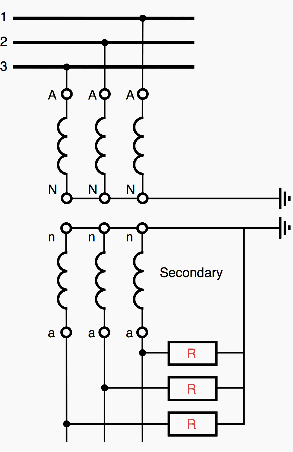
VTs with one secondary winding:
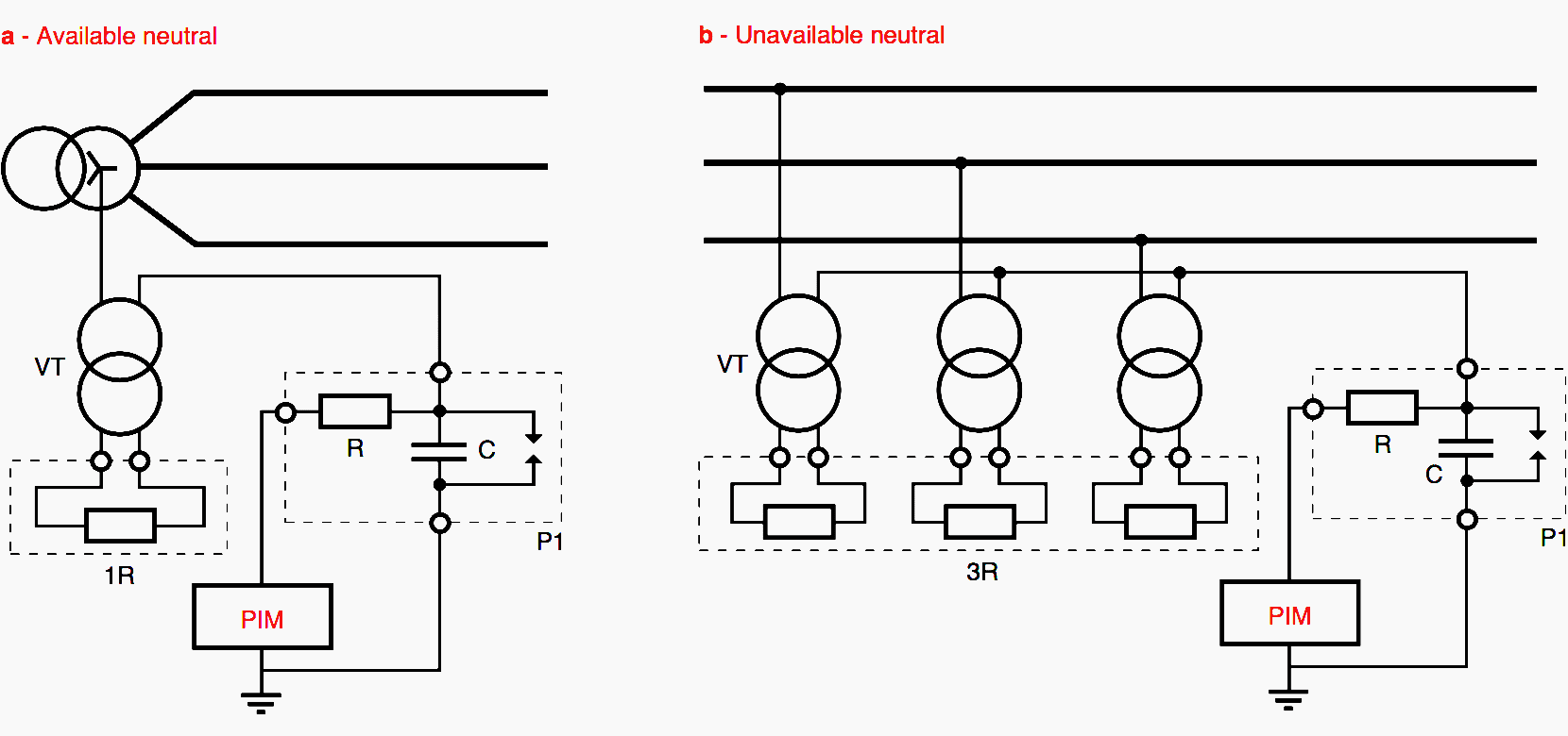
A damping resistor R is connected to the secondary of each VT (see figure 1 below), if consumption downstream of the VT is not sufficient. In this case the resistors continuously absorb power as soon as the VTs are energized.
The recommended minimum values for the resistance R and power PR of this resistance are:
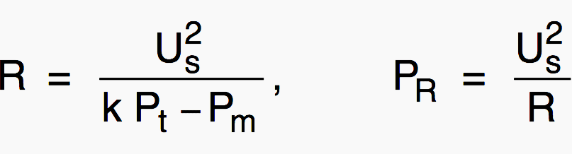
where:
- Us – Rated secondary voltage (V),
- k – Factor between 0.25 and 1 such that errors and service conditions remain within the limits specified by standard IEC 186 (k Pt is for example around 30 W for a 50 VA rated output).
- Pt – VT rated output (VA),
- Pm – Power required for measurement (VA).
The advantage of this damping device is that it does not affect measurement accuracy or introduce losses in normal (balanced) operating conditions, but only in unbalanced conditions in order to damp the phenomenon.
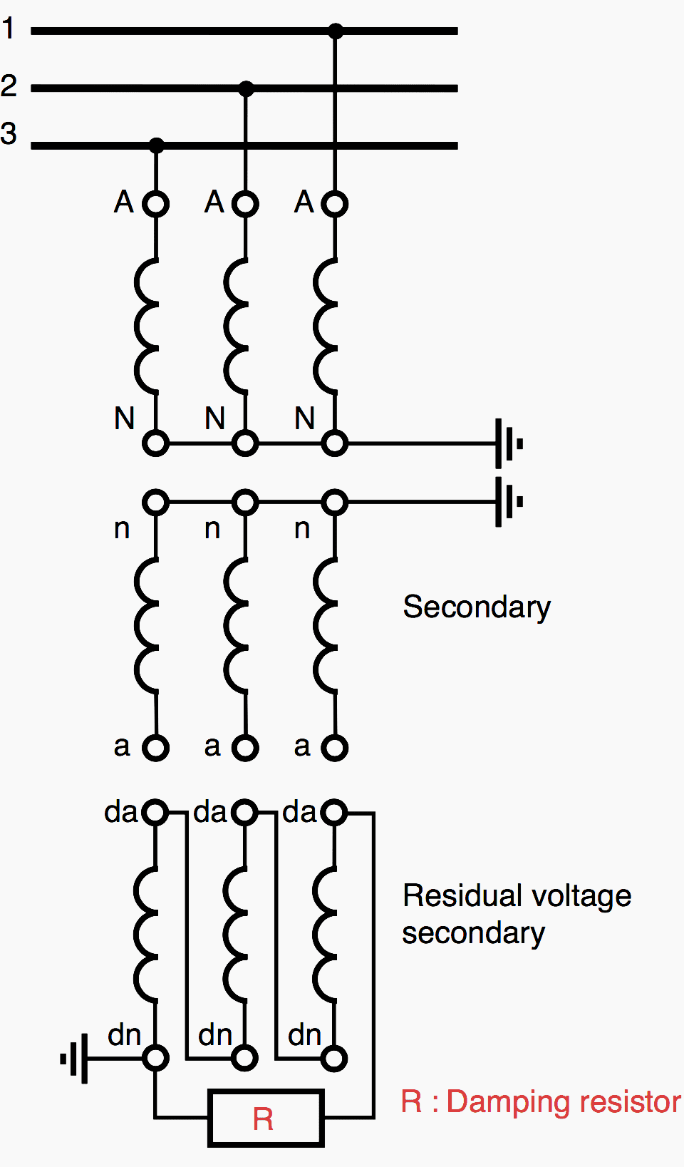
The recommended minimum values for the resistance R and power PR of this resistance are:
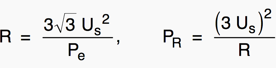
where:
- Us – Rated voltage of the VT secondary, connected to the resistance (V)
- Pe – Rated thermal burden of the VT secondary winding concerned by the resistance (VA).
The rated thermal burden (in VA) is the apparent power that can be supplied by the VT to the secondary without exceeding the limits of normal temperature rise, without precision requirements. Resistance R must be chosen to ensure permanent dissipation of power PR.
For example:
TT = 1000 / √3 – 100 / √3 – 100/3 V
Pe = 100 VA
(Us = 100/3)
R = (3 × √3 × (100/3)2) / 100 = 57.7 Ω
PR = (3 × 100/3)2 / 57.7 = 173 W
(standardised value immediately above 57.7Ω / 2 × 120Ω; 2×140W)
Configuration #2 – Transformer accidentally energized
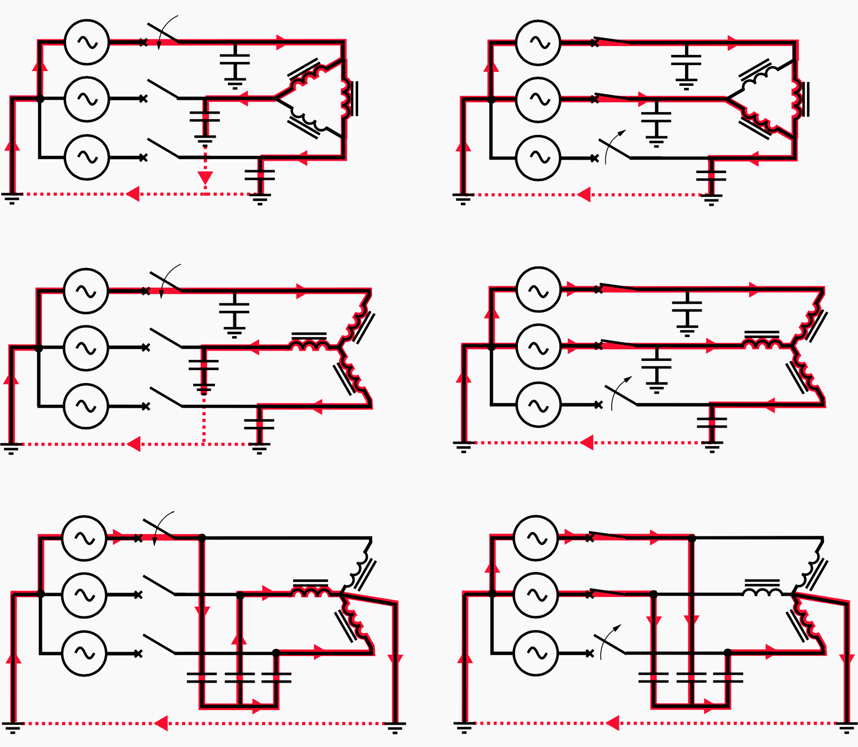
To prevent ferroresonance occurring on a transformer accidentally energized in only one or two phases (see figure 3), practical solutions consist of:
- Lowering the value of the capacitance between the circuit breaker and transformer below its critical value by using, for example, a circuit breaker cubicle closer to the transformer or placing circuit breakers just upstream of the transformers and closing them only when voltage has been restored to all three phases.
- Avoiding use of transformers delivering an active power which is lower by 10% than its rated apparent power.
- Avoiding no-load energizing.
- Prohibiting single-phase operations or fuse protection, blowing of which results in single-pole breaking,
- Prohibiting live work on a cable-transformer assembly when the cable length exceeds a certain critical length,
- Resistance-earthing of the supply substation neutral,
- Solidly earthing of the neutral (permanently or only during energizing and de-energizing operations) of a transformer whose primary is wye-connected (available neutral).
Configuration #3 – Case of isolated neutral systems
To avoid risk of ferroresonance with over-inductive Permanent Insulation Monitor (PIMs), an impedance can be installed between the transformer neutral and earth. This is the “impedant neutral” solution.
An impedance whose purely resistive value at 50 Hz is around 1500 Ω is recommended for a short LV power system supplied by an MV/LV substation .
The star point of the primaries of all other wye-connected VTs connected to the same isolated neutral system must also be earthed by means of a capacitance (P1 plate). This measure is often overlooked in extensions and sub-switchboards.
Config. #4 – MV power systems earthed through reactor
Case of MV power systems earthed through a reactor (see figure 5). The following measures can be taken in resonant earthed systems:
- Overcompensate the power frequency capacitance component of the earth-fault current by detuning the neutral earthing reactance,
- Add a resistive component to increase earth coil losses.
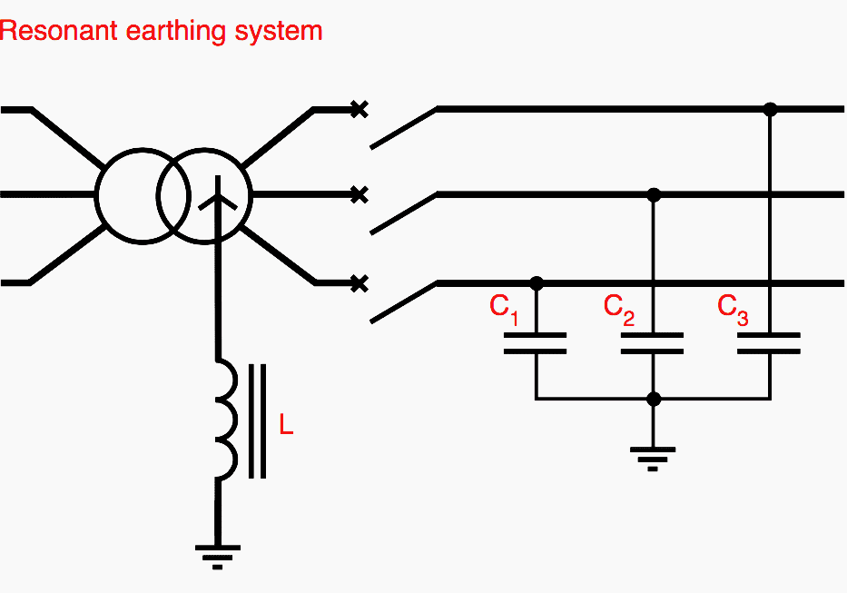
The measure taken must not, however, affect self-extinguishing of earth faults which is one of the aims of the resonant earthing system.
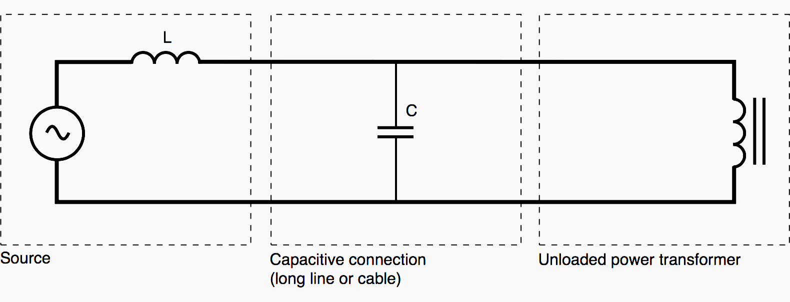
Config. #5 – Transformer fed through a capacitive power system
As regards a transformer fed through a capacitive power system (see figure 6 below), the best solution consists of avoiding risky configurations when active power delivery is less than 10 % of the transformer rated power.
This risk is considerable during low load periods (holidays, night time).
Ferroresonance in distribution transformers (VIDEO)
Reference // Ferroresonance by Ph. Ferracci (Schneider Electric)
Related electrical guides & articles


Edvard Csanyi
Hi, I'm an electrical engineer, programmer and founder of EEP - Electrical Engineering Portal. I worked twelve years at Schneider Electric in the position of technical support for low- and medium-voltage projects and the design of busbar trunking systems.I'm highly specialized in the design of LV/MV switchgear and low-voltage, high-power busbar trunking (<6300A) in substations, commercial buildings and industry facilities. I'm also a professional in AutoCAD programming.
Profile: Edvard Csanyi

The IEC says this “shall be limited” – what is the reference for this? Is there any other Codes or standards that deal with damping ferroresonance?
I have real experience of resolving ferroresonance due to 10,553 VFDs on only system and its not on your list.
Ian
We encounter one application question about ferroresonance VT from Power Company.
Could you email me and offer us some professional suggestion?
Appreciate for your early reply.
Hi Edvard,
An “active resistor” topology (the damping resistor is connected to VT secondary via anty-parallel thyristors) has been proposed in some publications. Do you have any experience on this matter that you can share?
Hola
En la figura 2,
¿Es necesario que la delta abierta esté conectada a tierra?
¿Que efectos tendría que esta delta opere sin la conexión a tierra?
Thanks a lot for your Practical information…
I have a experience a bout this issue….
I guess One of my power tap winding transformer damaged from ferroresonance Last year….
Much of this information is drawn from Schneider’s Cahier Technique No. 190, “Ferroresonance”, by Philippe Ferracci.
what will be multiplying factor when a 1200/1 CT is connected to -/5 meter
Hallo Rajnessh – 6000 will be the primary ratio if you are measuring 1200/1 CT by -/5 CT