
Estimated Study Time: 39 minutes
Voltage fluctuations, flicker & step changes
To be honest, power grids are not perfect; on the contrary, most of them are far, far away from perfect, or even good. Therefore, what makes a power grid perfect or good? Well, in a power industry, maintaining voltage quality during equipment energization or switching is crucial for system reliability and consumer comfort.
 Preventing new grid connections from creating unacceptable disturbances for other users
The Engineering Recommendation P28, issued by the Energy Networks Association (ENA), provides standardized guidance for assessing and controlling voltage fluctuations, flicker, and step changes caused by industrial or commercial equipment.
P28 ensures that new network connections—such as large transformers, motors, welding machines, or standby generators—do not create unacceptable disturbances for other users. It defines planning limits for voltage variations, sets assessment methodologies, and prescribes reporting formats for compliance.
The document primarily addresses three disturbance types:
- Voltage Step Change: sudden variations during switching or load transfer.
- Voltage Flicker: cyclic voltage changes that may cause visible light flicker or process instability.
- Inrush Current Impacts: temporary voltage dips during transformer or motor energization.
P28 study introduces flicker severity indices—Pst (short-term) and Plt (long-term)—to quantify these effects and compare them with acceptable limits. The standard also outlines a structured study process involving data collection, network modelling, simulation of voltage dips or flicker, and comparison with P28 thresholds.
Clear compliance reporting is central to P28, ensuring transparency between developers and Distribution Network Operators (DNOs). Through case studies—like transformer inrush, welding loads, or generator trips—P28 demonstrates practical methods for analyzing and reducing voltage disturbances.
- What Does P28 Study Cover?
- Methodology of a P28 Study:
- Mitigation Strategies in P28 Studies:
- Compliance & Reporting in P28 Studies:
- Case Study #1 – Welding Load in a Manufacturing Plant
- Case Study #2 – Transformer Inrush
- Case Study #3 – Generator (STOR) Trip
- Event Frequency Categories in P28 Studies – Frequent, Infrequent, and Very Infrequent:
- Practical Role in Power System Studies
- Attachment (PDF) 🔗 Download ‘Guide to Power-line Communication (PLC) Systems: Theory and Applications’
1. What Does P28 Study Cover?
ENA Engineering Recommendation P28 is a standard that sets planning limits and assessment methods for voltage fluctuations on public electricity networks caused by industrial, commercial, and domestic equipment. Its scope ensures that electrical disturbances remain within tolerable limits for both network operators and end users.
The standard addresses several key areas:
1.1 Voltage Step Change
A voltage step change occurs when there is a sudden, sustained shift in network voltage—usually caused by events such as transformer energization, generator tripping, or large motor starting.
- Example: Energizing a large transformer may cause an immediate drop in voltage (e.g., 2–5%), which then recovers as the system stabilizes.
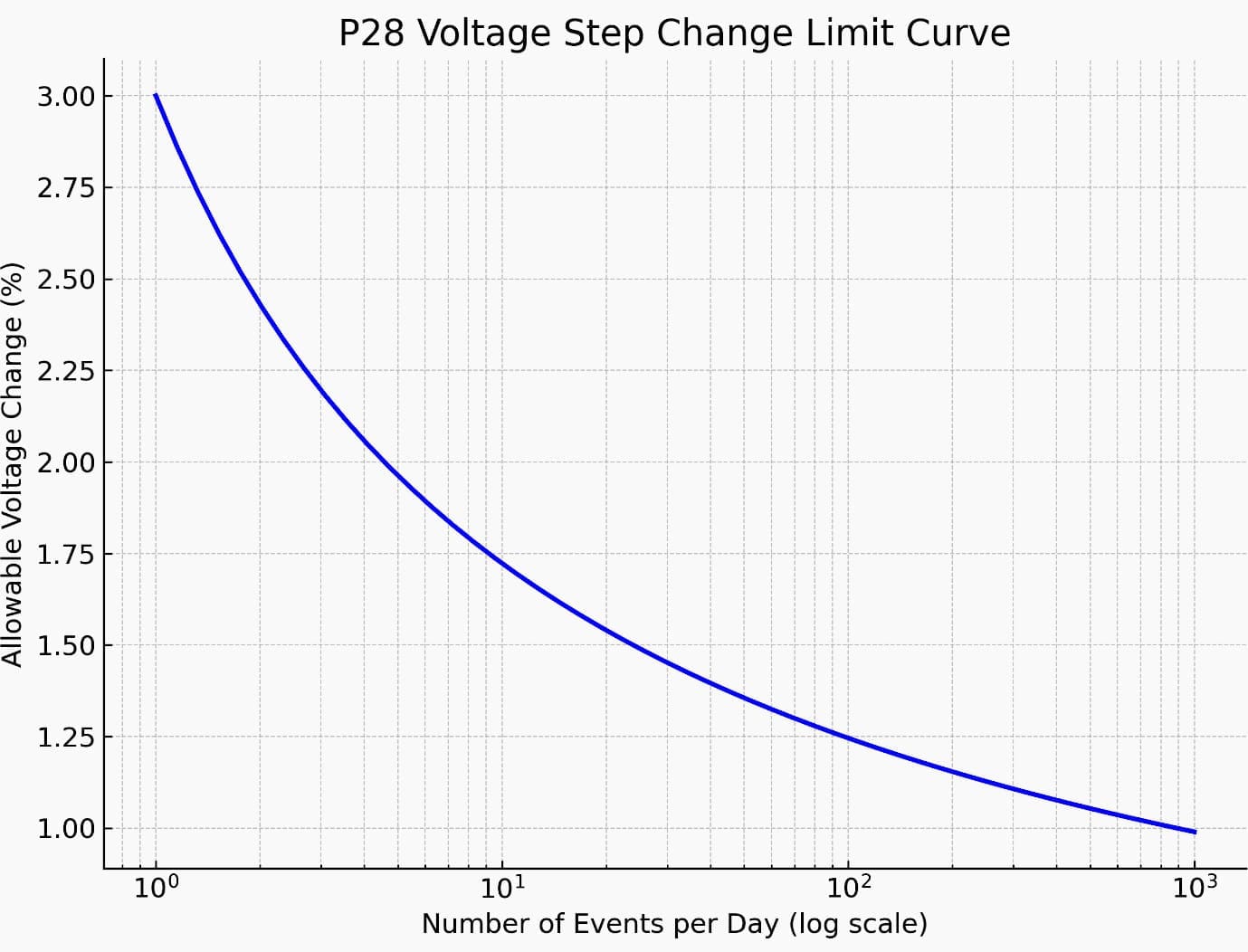
- Why it matters: If voltage steps are too large, they can trigger nuisance tripping in sensitive devices or degrade equipment performance. P28 prescribes allowable step limits based on event frequency, with tighter limits for frequent events.
Figure 1 – Voltage Step Change Limit Curve
1.2 Voltage Flicker (Short-Term and Long-Term)
Voltage flickers refer to rapid, repetitive voltage variations that cause visible light flicker or equipment interference.
- Short-Term Flicker (Pst): A statistical measure over a 10-minute window. It reflects immediate, noticeable flicker effects.
- Long-Term Flicker (Plt): Calculated over a two-hour window, averaging multiple Pst values to represent ongoing discomfort or disturbance.
- Example: Arc welding machines in a factory may cause noticeable flicker in lighting when multiple welders strike arcs simultaneously.
- Why it matters: Excessive flicker can cause visual discomfort, reduce productivity, and trigger public complaints.
1.3 Inrush Current Impacts
Inrush current is the high surge of current drawn when equipment such as transformers or large motors is first energized.
- Example: Transformer inrush can be 6–12 times its rated current for a short duration due to magnetic core saturation.
- Impact on voltage: The sudden demand can cause a measurable dip in network voltage at the Point of Common Coupling (PCC), contributing to both step changes and flicker.
- P28 role: Specifies how to model these effects and compare them against allowable voltage disturbance envelopes.
Figure 2 – Power supply voltage at switch-on and inrush current
1.4 Worst-Case Energization Scenarios
P28 study assessments are based on worst-case conditions to ensure network resilience. This includes:
- Maximum possible disturbance load operating at once.
- Highest residual flux assumption for transformer energization.
- Weakest network condition (lowest short-circuit level).
- Worst-case timing relative to other events.
Why this is important: Designing for the worst case ensures that real-world operation will remain compliant even under extreme but plausible conditions.
1.5 Flicker Severity Metrics (Pst and Plt)
P28 adopts IEC 61000-4-15 methodology for flicker measurement, using two main metrics:
- Pst (Short-Term Flicker Severity): Limit is 1.0 at the PCC.
- Plt (Long-Term Flicker Severity): Limit is 0.8 at the PCC.
Compliance is assessed by measuring these values or simulating them using load profiles, ensuring that the flicker impact is acceptable for all connected customers.
P28 study does not only deal with obvious flicker complaints—it provides a quantitative framework for assessing a wide range of voltage disturbances. From one-off events like transformer energization to repetitive fluctuations from industrial machinery, the standard ensures a consistent, objective basis for connection approvals and system design in the UK.
Table 1 – Summary of Disturbance Types Covered by ENA EREC P28
| Disturbance Type | Typical Causes | Measurement / Assessment Method | P28 Planning Limit |
| Voltage Step Change | Large motor starting, transformer energization, generator trip | Measure voltage change at PCC in %, or simulate in Dig SILENT, ETAP, or EMTP | Varies by event frequency (e.g., ≤ 3% for frequent events) |
| Short-Term Flicker (Pst) | Arc welders, fluctuating industrial loads, inverter-based generation | Measured using IEC 61000-4-15 flicker meter over 10 minutes | Pst ≤ 1.0 |
| Long-Term Flicker (Plt) | Continuous operation of flicker-causing loads over long periods | Average of multiple Pst values over 2 hours | Plt ≤ 0.8 |
| Inrush Current | Transformer magnetization, motor starting | Model inrush current and resulting voltage dip; compare with P28 disturbance envelopes | Voltage dip must remain within envelope for given event frequency |
| Worst-Case Energization | Simultaneous energization of large equipment under weakest network condition | Simulate with highest residual flux, weakest fault level, and largest disturbance load | Voltage disturbance must remain within P28 limits under worst-case conditions |
2. Methodology of a P28 Study
A P28 study is a structured engineering assessment carried out to evaluate whether a proposed or existing electrical installation will cause voltage disturbances—such as flicker, step changes, or inrush dips—that remain within the limits set out in ENA EREC P28. The process typically follows four main stages:
2.1 Data Gathering
Accurate modelling begins with high-quality input data. This stage involves collecting all relevant network and equipment parameters from the Distribution Network Operator (DNO), project specifications, and equipment data sheets.
Key data includes:
- Network impedance at the Point of Common Coupling (PCC): crucial for understanding how the network will respond to disturbances.
- Source short-circuit level: defines the strength of the network and its ability to absorb sudden changes in load without large voltage deviations.
- Transformer parameters: such as rated power, impedance (%Z), inrush current multipliers, winding configuration, and residual flux assumptions.
- Load characteristics: including motor starting currents, duty cycles, and operational frequency of disturbance-causing equipment.
2.2 Simulation and Modelling
Once the input data is verified, a detailed simulation model is built to replicate the electrical behavior of the system under study. Commonly used software includes:
- DIgSILENT Power Factory: widely used for voltage dip and flicker simulations.
- ETAP: useful for steady-state and transient studies, especially motor starting analysis.
- PSCAD / EMTP: preferred for high-fidelity transient inrush modelling, capturing non-linear magnetic saturation effects in transformers.
The model incorporates the P28 event categorization (frequent, infrequent, or very infrequent) to ensure results are benchmarked against the correct disturbance envelope.
Watch Video – Load Flow using ETAP Exercise
2.3 Calculation of Voltage Dip or Flicker Severity
Using the simulation results, the voltage disturbance at the PCC is calculated. Depending on the study type:
- For step changes, the immediate post-event voltage drop (percentage) is measured.
- For flicker, the Pst (short-term) and Plt (long-term) values are calculated using IEC 61000-4-15 methodology.
- For inrush events, the peak and RMS voltage dips over defined time intervals (e.g., 30 ms, 100 ms, 2 s) are extracted.
2.4 Comparison with P28 Limits
Finally, the calculated results are compared against the ENA P28 planning limits for the relevant event frequency. This determines compliance and identifies any mitigation requirements.
If the results exceed the permissible limits, possible mitigation measures include:
- Staggering motor starts or transformer energizations.
- Increasing network fault level (e.g., by reinforcing the network connection).
- Adding soft starters or variable frequency drives (VFDs) for motors.
- Using pre-insertion resistors for transformer energization.
Table 2 – Maximum voltage dip results for event categories
| Event Category | Max Voltage Dip (30 ms) | Max Voltage Dip (100 ms) | Max Voltage Dip (2 s) |
| Frequent | 6% | 3% | – |
| Infrequent | 10% | – | 3% |
| Very Infrequent | 12% | 10% | 3% |
3. Mitigation Strategies in P28 Studies
When a proposed installation is found to exceed the permissible limits set out in ENA EREC P28, it is essential to consider mitigation strategies to bring the disturbance levels within compliance.
These measures aim to reduce the magnitude and/or frequency of voltage dips, flicker, and step changes at the Point of Common Coupling (PCC).
3.1 Controlled Switching for Transformers
Principle:
Controlled switching uses synchronized circuit breaker operation to close at the optimal point on the voltage waveform, minimizing transformer inrush current.
Application:
- Particularly effective for large power transformers where energization inrush is a major contributor to voltage step changes.
- Requires circuit breakers equipped with point-on-wave controllers.
Benefits:
- Reduces inrush current magnitude by up to 90%.
- Minimizes mechanical and thermal stress on transformer windings.
- Improves compliance with P28 voltage disturbance limits.
Suggested Guide – Power transformer energization problems and modeling for calculation of inrush currents
Power transformer energization problems and modeling for calculation of inrush currents
3.2 Sequential Energization
Principle:
Avoids energizing multiple large loads or transformers at the same time by staggering operations over defined intervals.
Application:
- Common in multi-transformer substations or industrial plants with several large motors.
- Simple operational control or automation can be used to ensure sequencing.
Benefits:
- Reduces cumulative voltage dips.
- Often the most cost-effective mitigation option with minimal hardware changes.
3.3 Pre-Insertion Resistors
Principle:
Temporary resistors are inserted into the circuit during transformer or reactor energization to limit the inrush current. The resistors are bypassed once steady-state conditions are achieved.
Application:
Suitable for EHV/HV transformer energization in substations where inrush can cause significant disturbance.
Benefits:
- Reduces voltage step change magnitude.
- Particularly useful for very infrequent events where controlled switching is not installed.
Figure 3 – Model of a circuit breaker with a Pre-Insertion Resistor
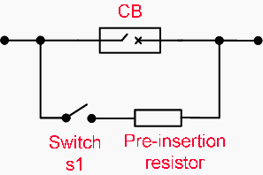
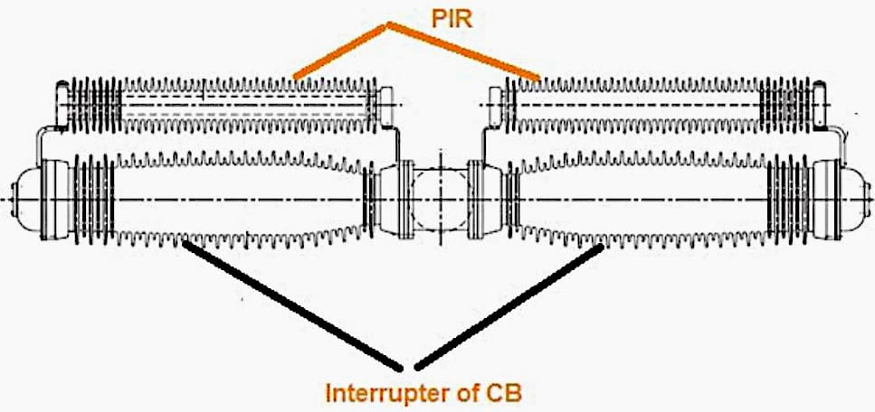
Figure 4 – Pre-Insertion Resistor attached to CB interruptor
3.4 Soft Starters and Variable Frequency Drives (VFDs) for Motors
Principle:
Soft starters gradually ramp up voltage during motor start-up, while VFDs control both voltage and frequency to limit inrush current and mechanical stress.
Application:
- Large industrial motors (>250 kW) starting Direct-On-Line (DOL) are prime candidates.
- It is particularly important where motors start frequently.
Related electrical guides & articles


Muhammad Kashif
Muhammad Kashif Shamshad is an Electrical Engineer and has more than 17 years of experience in operation & maintenance, erection, testing project management, consultancy, supervision, and commissioning of Power Plant, GIS, and AIS high voltage substations ranging up to 500 kV HVAC & ±660kV HVDC more than ten years experience is with Siemens Saudi Arabia.Profile: Muhammad Kashif
