Typical distribution circuit
Distribution circuits come in many different configurations and circuit lengths. Most share many common characteristics. Figure 1 shows a typical distribution circuit, and Table 1 shows typical parameters of a distribution circuit.
A feeder is one of the circuits out of the substation. The main feeder is the three-phase backbone of the circuit, which is often called the mains or mainline. The mainline is normally a modestly large conductor such as a 500- or 750-kcmil aluminum conductor.
Utilities often design the main feeder for 400 A and often allow an emergency rating of 600 A. Branching from the mains are one or more laterals, which are also called taps, lateral taps, branches, or branch lines. These laterals may be single-phase, two- phase, or three-phase.
The laterals normally have fuses to separate them from the mainline if they are faulted.
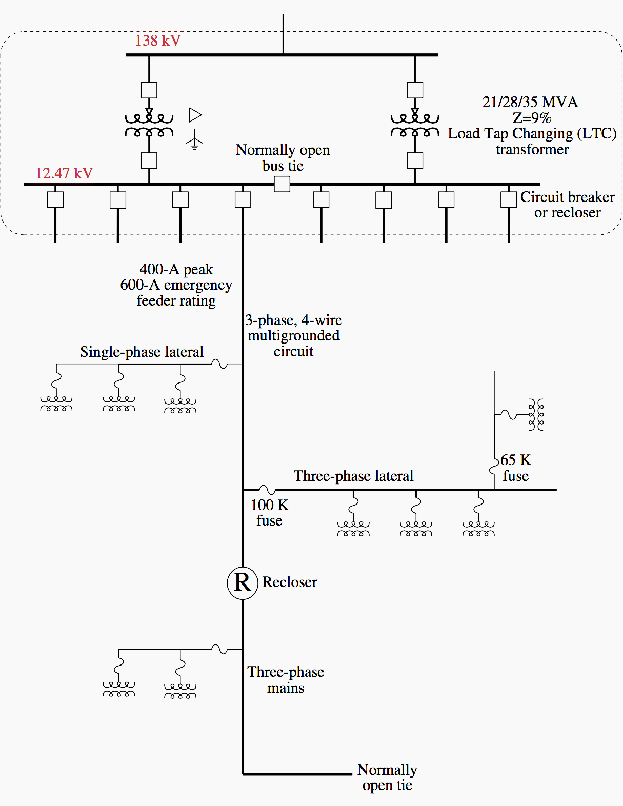

The most common distribution primaries are four-wire, multi-grounded systems: three-phase conductors plus a multigrounded neutral. Single-phase loads are served by transformers connected between one phase and the neutral.
The neutral acts as a return conductor and as an equipment safety ground (it is grounded periodically and at all equipment).
Table 1 – Typical Distribution Circuit Parameters
| Most common value | Other common values | |
| Substation characteristics | ||
| Voltage | 12.47 kV | 4.16, 4.8, 13.2, 13.8, 24.94, 34.5 kV |
| Number of station transformers | 2 | 1 – 6 |
| Substation transformer size | 21 MVA | 5 – 60 MVA |
| Number of feeders per bus | 4 | 1 – 8 |
| Feeder characteristics | ||
| Peak current | 400 A | 199 – 630A |
| Peak load | 7 MVA | 1 – 15 MVA |
| Power factor | 0.98 lagging | 0.8 lagging / 0.95 leading |
| Number of customers | 400 | 50 – 5000 |
| Length of feeder mains | 4 mi | 2 – 15 mi |
| Length including laterals | 8 mi | 4 – 25 mi |
| Area covered | 25 mi2 | 0.5 – 500 mi2 |
| Mains wire size | 500 kcmil | 4/0 – 795 kcmil |
| Lateral tap wire size | 1/0 | #4-2/0 |
| Lateral tap peak current | 25 A | 5 – 50 A |
| Lateral tap length | 0.5 mi | 0.2 – 5 mi |
| Distribution transformer size (1ph) | 25 kVA | 10 – 150 kVA |
A single-phase line has one phase conductor and the neutral, and a two-phase line has two phases and the neutral. Some distribution primaries are three-wire systems (with no neutral). On these, single-phase loads are connected phase to phase, and single-phase lines have two of the three phases.
There are several configurations of distribution systems. Most distribution circuits are radial (both primary and secondary).
Radial circuits have many advantages over networked circuits including:
- Easier fault current protection
- Lower fault currents over most of the circuit
- Easier voltage control
- Easier prediction and control of power flows
- Lower cost
Distribution primary systems come in a variety of shapes and sizes (Figure 2). Arrangements depend on street layouts, the shape of the area covered by the circuit, obstacles (like lakes), and where the big loads are.
A common suburban layout has the main feeder along a street with laterals tapped down side streets or into developments.
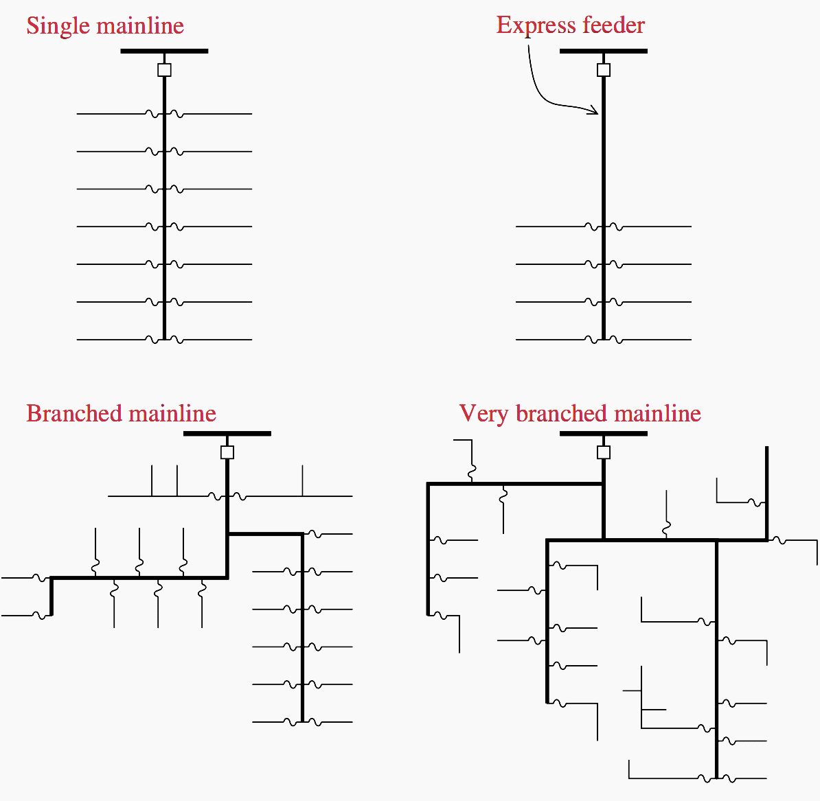

Radial distribution feeders may also have extensive branching – whatever it takes to get to the loads. An express feeder serves load concentrations some distance from the substation. A three-phase mainline runs a distance before tapping loads off to customers.
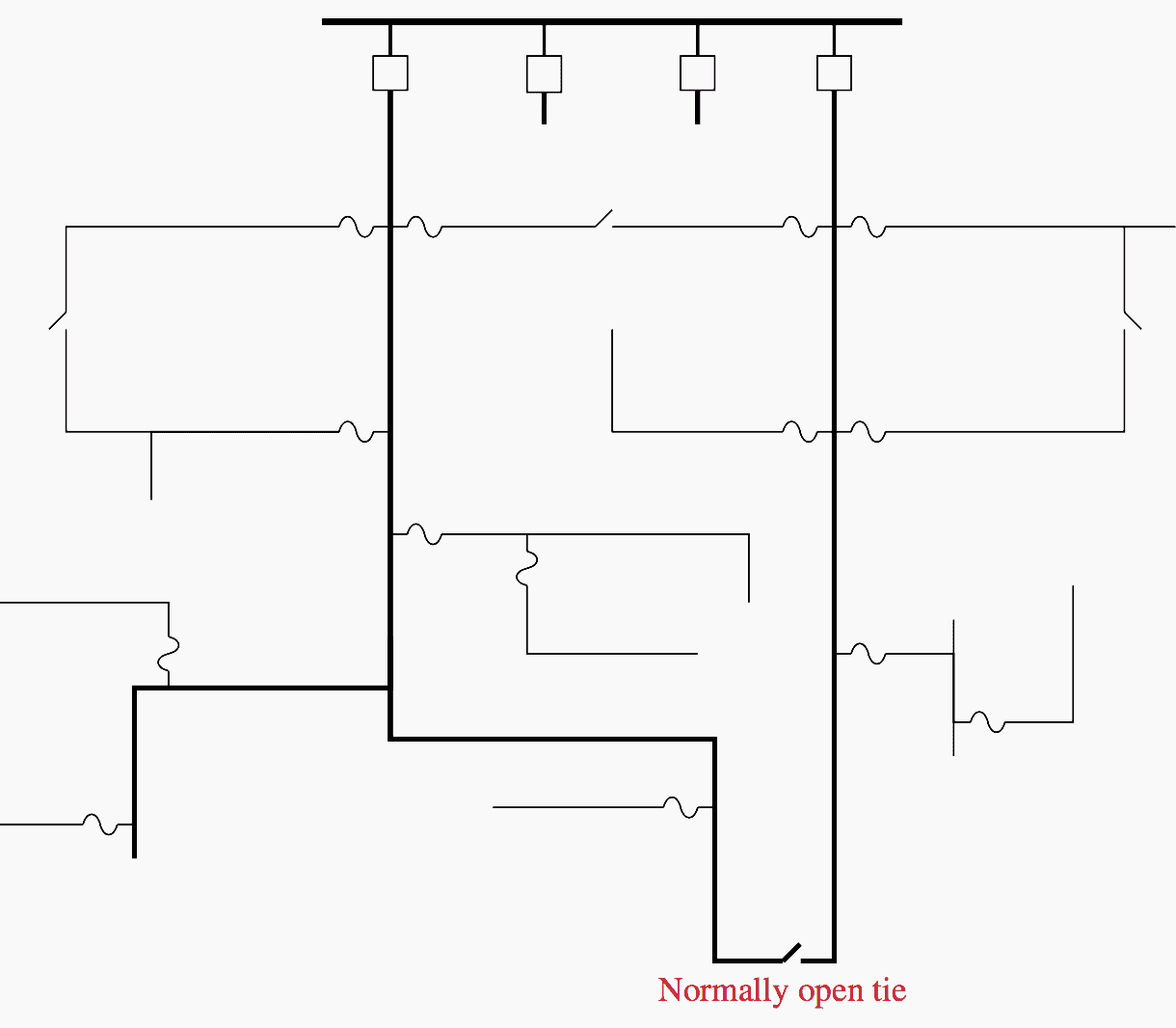
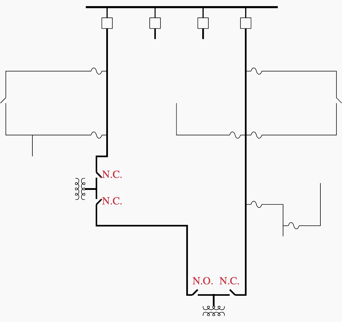
For improved reliability, radial circuits are often provided with normally open tie points to other circuits as shown in Figure 3. The circuits are still operated radially, but if a fault occurs on one of the circuits, the tie switches allow some portion of the faulted circuit to be restored quickly.
Normally, these switches are manually operated, but some utilities use automated switches or reclosers to perform these operations automatically.

A primary-loop scheme is an even more reliable service that is sometimes offered for critical loads such as hospitals. Figure 4 shows an example of a primary loop. The key feature is that the circuit is “routed through” each critical customer transformer.
Primary-loop systems are sometimes used on distribution systems for areas needing high reliability (meaning limited long-duration interruptions). In the open-loop design where the loop is left normally open at some point, primary-loop systems have almost no benefits for momentary interruptions or voltage sags. They are rarely operated in a closed loop.

A widely reported installation of a sophisticated closed system has been installed in Orlando, FL, by Florida Power Corporation. An example of this type of closed-loop primary system is shown in Figure 4.
Faults on any of the cables in the loop are cleared in less than six cycles, which reduces the duration of the voltage sag during the fault (enough to help many computers). Advanced relaying similar to transmission-line protection is necessary to coordinate the protection and operation of the switchgear in the looped system.
The relaying scheme uses a transfer trip with permissive over-reaching (the relays at each end of the cable must agree there is a fault between them with communications done on fiberoptic lines).
A backup scheme uses directional relays, which will trip for a fault in a certain direction unless a blocking signal is received from the remote end (again over the fiberoptic lines).
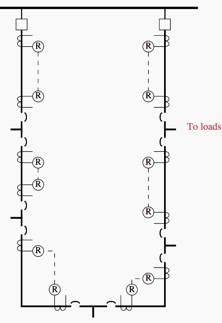

Critical customers have two more choices for more reliable service where two primary feeds are available. Primary selective and secondary selective schemes both are normally fed from one circuit (see Figure 5 above).
So, the circuits are still radial. In the event of a fault on the primary circuit, the service is switched to the backup circuit. In the primary selective scheme, the switching occurs on the primary, and in the secondary selective scheme, the switching occurs on the secondary. The switching can be done manually or automatically, and there are even static transfer switches that can switch in less than a half cycle to reduce momentary interruptions and voltage sags.
The normally closed switch on the primary-side transfer switch opens after sensing a loss of voltage. It normally has a time delay on the order of seconds – enough to ride through the distribution circuit’s normal reclosing cycle. The opening of the switch is blocked if there is an overcurrent in the switch (the switch doesn’t have fault interrupting capability). Transfer is also disabled if the alternate feed does not have proper voltage.
The switch can return to normal through either an open or a closed transition. In a closed transition, both distribution circuits are temporarily paralleled.
Reference // Electric power distribution equipment and systems / T.A. Short (Purchase at Amazon)





Hi thanks for sharing knowledge
All distribution circuts coming out of a substation must have at least, how many wires??
A. 2 wires
B. 3 wires
C. 4 wires
D. Neutral wire
All distribution line circuits coming out of a substation must have 4 wires that means 1-3 Are phases and 4 is neutral wire
Hi thanks for sharing power distribution information. I am working in power distribution company in IESCO from pakistan.
how to calculate the short circuit current at bus 135 if the is motors 400 volt and total load of 1Mkva thank you
Great information, easy to read & understand. It’ll be nice if you have information concerning revamping of distribution feeders, feeding from different substations or paralleling them, concerns, cable sizes, equipment involved to achieve this and protection concerns..
Thank You!.
Carlos.
The article is comprehensive and easily understandable. Thank you for sharing knowledge.