Preventing an interruption of service
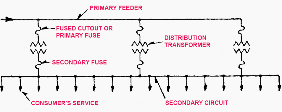
As we already know, distribution transformers step down from the distribution or primary feeder voltage to the utilization voltage. They are connected to the primary feeder, sub-feeders, and laterals through primary fuses or fused cutouts. The primary fuse disconnects its associated distribution transformer from the primary feeder when a transformer fault or low-impedance secondary-circuit fault occurs. Reclosers are not covered in this article.

The blowing of the primary fuse prevents an interruption of service to other loads supplied over the feeder, but interrupts service to all consumers supplied through its transformer. Fused cutouts (shown in Figure 1), which are normally closed, provide a convenient means for disconnecting small distribution transformers for inspection and maintenance.
Satisfactory overload protection of a distribution transformer cannot be obtained with a primary fuse, because of the difference in the shape of its current-time curve and the shape of the safe current-time curve of a distribution transformer. The shapes of the two curves are such that if a small enough fuse is used to provide complete overload protection for the transformer much valuable transformer overload capacity is lost, because the fuse blows and prevents its being used. Such a small fuse also frequently blows unnecessarily on surge currents.
Distribution transformers connected to overhead open-wire feeders are often subjected to severe lightning disturbances. To minimize insulation breakdown and transformer failures from lightning, lightning arresters are ordinarily used with these transformers.


The secondary leads of a distribution transformer are usually solidly connected to radial secondary circuits from which the consumers services are tapped as shown in Figure 1. This means that no protection is provided the transformer against overloads and high-impedance faults on its secondary circuits. Relatively few distribution transformers are burned out by overloads.
This is largely because distribution transformers are applied so that full advantage is rarely taken of their overload capacity.
Fuses in the secondary leads of distribution transformers are little if any more effective in preventing transformer burnouts than are primary fuses and for the same reasons. The proper way to obtain satisfactory protection for a distribution transformer against overloads and high-impedance faults is by means of a circuit breaker in the secondary leads of the transformer. The tripping curve of this circuit breaker must be properly coordinated with safe current-time curve of the transformer.
The primary fuse must be coordinated with the secondary breaker so that the breaker tripe on any current that can pass through it before the fuse is damaged.


Faults on a consumer’s service connection from the secondary circuit to the service switch are so rare that the use of a secondary fuse, where the service connection taps onto the secondary circuit, cannot be economically justified except in unusual cases such as large services from underground secondaries.
As has been previously pointed out the allowable voltage drop from the point where the first distribution transformer connects to the primary feeder to the service switch of the last consumer supplied over the feeder should be economically divided among the primary feeder, the distribution transformer, the secondary circuit, and the consumer’s service connection.
Voltage variation
Assuming a maximum voltage variation of about 10% at any consumer’s service switch the division of this drop among the various parts of the system, at times of full load, may be about:
- 2% voltage variation in the primary feeder between the first and last transformers,
- 2.5% voltage variation in the distribution transformer,
- 3% voltage variation in the secondary circuit, and
- 0.5% voltage variation in the consumer’s service connection.
The fact that the voltage at the primary of the first distribution transformer cannot ordinarily be maintained exactly accounts for the other 2%.
While these figures are typical for overhead systems supplying residential loads, they can be expected to differ considerably on underground systems where cable circuits and large distribution transformers are used or where industrial and commercial loads are supplied.
The economic size of distribution transformer and secondary-circuit combination for any uniform load density and type of construction at any particular market prices can readily be determined once the total allowable voltage drop in these two parts of the system is determined.
If the transformer is too large the secondary circuit cost and total cost is excessive, and if the transformer is too small the transformer cost and total cost is too large.


As in any other part of the distribution system, load change or load growth must be considered and provided for in the distribution transformers and secondary circuits. Also, as with other parts of the distribution system the distribution transformers and secondary circuits are not installed to serve only the loads existing at the time of their installation but some future loads as well.
It is not economical to make too much allowance for growth, however.
This also reduces the load on the secondary circuit of the overloaded transformer and improves the overall voltage regulation. If the load in the area is reasonably uniform transformers may have to be installed on both sides of the overloaded transformer in a relatively short time to maintain satisfactory voltage conditions and prevent overloading a part of the secondary circuit.
The same result can be obtained, however, by installing one new transformer and moving the overloaded transformer so that it feeds into the center of its shortened secondary circuit.


With the distribution transformers and secondary circuits arranged as shown in Figure 1 any one load is supplied through only one transformer and in only one direction over the secondary circuit. Because of this a suddenly applied load, such as the starting of a motor, on a consumer’s service can cause objectionable light flicker on other consumers’ services fed from the same transformer.
The increasing use in residential areas of motor-driven appliances, such as washers, refrigerators, forced-air heating systems, and air-conditioning equipment, is resulting in a considerable number of light-flicker complaints.
In some areas light flicker and not voltage regulation may be the determining factor in the size and arrangement of transformers and secondary circuits. The banking of distribution transformers is usually the best and most economical means of improving or eliminating light flicker.
Because of this similarity in secondary-circuit arrangements a banked-transformer layout is sometimes incorrectly referred to as a secondary network system. Banked transformers, because they are connected to and supplied over a single radial-primary feeder, are a form of radial distribution system; whereas a secondary network loop or grid is supplied over two or more primary feeders which results in much greater service reliability.
Banking of distribution transformers is not new and has been used on a number of systems for many years.


The conversion from the usual radial secondary circuit arrangement of Figure 1 to the banked-transformer arrangement of Figures 5 and 6 can usually be made simply and cheaply by closing the gaps between the radial secondaries of a number of the transformers associated with the same primary feeder and installing the proper primary and secondary fuses.
Two major forms of protection have been used when banking distribution transformers. The arrangement shown in Figure 5 is probably the oldest and most common. The distribution transformers are connected to their primary feeder through primary fuses or fused cutouts. These fuses should blow only on a fault in their associated transformer.
All transformers are connected to the common secondary circuit through secondary fuses.
To prevent frequent blowing of secondary fuses on secondary-circuit faults these fuses should have relatively long blowing times on all fault currents. Their blowing times should not be so long, however, as not to provide some degree of protection to their transformers against secondary faults that do not burn clear or require an unusually long time to do so.
As previously stated secondary fuses cannot be expected to protect transformers satisfactorily against overloads and high-impedance secondary faults. The use of a secondary breaker having the proper current-time characteristics is preferable to secondary fuses when banking transformers as shown in Figure 5 because greater protection is afforded the transformer against overloads and high-impedance faults.
The secondary fuses or breakers should open in less time than the primary fuses on any possible current so as to prevent the blowing of primary fuses on a secondary fault.
Experience indicates that, where a careful study of the fault currents to be expected is made and the primary and secondary fuses are properly selected, this method of banking operates with very little trouble. Occasionally a secondary-circuit fault causes the blowing of all secondary fuses or the blowing of some secondary fuses and the burning out of a few transformers. When this happens the extent of the service interruption is much greater than when radial secondary circuits are used.
The transformer banking arrangement shown in Figure 6 is preferable to that just described because there is no danger of a complete service interruption to the banked area by a secondary fault.


It should be remembered, however, in considering either of these arrangements that the possibility of a secondary fault is considerably less than that of a primary fault and that secondary faults are ordinarily infrequent. In this second arrangement the distribution transformers are connected to the primary feeder through primary fuses just as in the first arrangement and for the same reason.
The transformers are connected solidly to the secondary circuit and the secondary circuit is sectionalized between transformers by secondary fuses. These fuses are selected so that for any secondary-circuit fault they will blow quicker than any primary fuse.
A secondary-circuit fault is usually burned clear; however, if the fault persists for an unusually long time it is cleared by the secondary fuses next to the faulty section and the primary fuse associated with the transformer connected to the faulty section. The secondary fuses are usually selected so that they operate even on a high-impedance fault, but the primary fuses are not for the reason previously discussed in connection with the radial-secondary circuits.
Thus even when a high-impedance fault occurs and hangs on, the secondary fuses adjacent to the faulty section blow and prevent interrupting service on the good secondary sections. The transformer associated with the faulty section in this case, however, will be burned out. In order to prevent this a secondary breaker whose current-time curve is coordinated with the safe current-time curve of the transformer can be used in the secondary leads of the transformer.
When such a breaker is used the secondary fuses must be selected so that their blowing times for all fault currents are less than the tripping times of the breakers.
Normally the two banking arrangements function alike. They reduce or eliminate light flicker and improve voltage regulation or permit reduction in the amount of transformer capacity necessary as compared with radial-secondary circuits. This improvement in voltage regulation or reduction in transformer capacity is the result of tying several radial-secondary circuits together and thus taking advantage of the diversity among a number of groups of consumers.
A considerable increase in the use of banked transformers can be expected in the future because these advantages often can be obtained at no increase in cost or a saving over the usual radial secondary-circuit arrangement.
Sources:
- Electrical T&D Reference by ABB
- Electrical power supply and distribution by Unified Facilities Criteria (UFC)


Good Morning,
I tried a couple of times to save this article to PDF but I was not able to. I became a premium member of EEP. For my understanding change articles to PDF is part of the subscription.
Please, let me know if I am missing something.
Thank you for your attention!
Hi Ruben,
I sent you an email a few hours ago with instructions on what to do to solve the issue. Did you receive it?
Dear respected sir,
Please send to me Gulf Transformer , and DG , equipments before commissing , how much should be Following values , please send to my email id , please send newly anything Electrical power electronics production equipment , and instruments,
Thanks you
Ramakrishna.A
9025421119 & what’s app