
Estimated Study Time: 40 minutes
Do’s & Don’ts in Primary Injection Testing
Primary injection testing is a vital procedure in the commissioning and maintenance of current transformers (CTs). These transformers are integral components of electrical systems, enabling precise measurement and effective protection of electrical currents. In this article, we will explore the fundamental concepts of primary injection testing and dive deep into the essential aspects of current transformer commissioning.
 Primary injection testing and CTs commissioning in power substations (for true engineers)
We’ll begin by understanding the primary and secondary sides of a current transformer. The primary side is where the current to be measured or protected flows, typically connected to the power system. On the other hand, the secondary side provides an output current proportional to the primary current, utilized for measurement or relaying purposes.
Distinguishing between these sides is crucial for comprehending the role of current transformers in electrical systems.
To facilitate a comprehensive understanding of current transformer commissioning, we’ll delve into essential terminology and key concepts. This includes exploring the significance of components such as the current transformer terminal box, which serves as a wiring hub for CT secondary connections, ensuring proper connectivity and control.
Local control cubicles (LCC) panels play a crucial role in centralized control and monitoring in substations and power plants. They provide a central hub for managing and monitoring various equipment, including current transformers, ensuring smooth operation and prompt response to abnormalities.
Furthermore, we will unveil the significance of polarity marking in current transformers, which ensures accurate connection and measurement. We shall explore the marking of primary polarity and the understanding of secondary polarity marking, shedding light on their importance in achieving precise results.
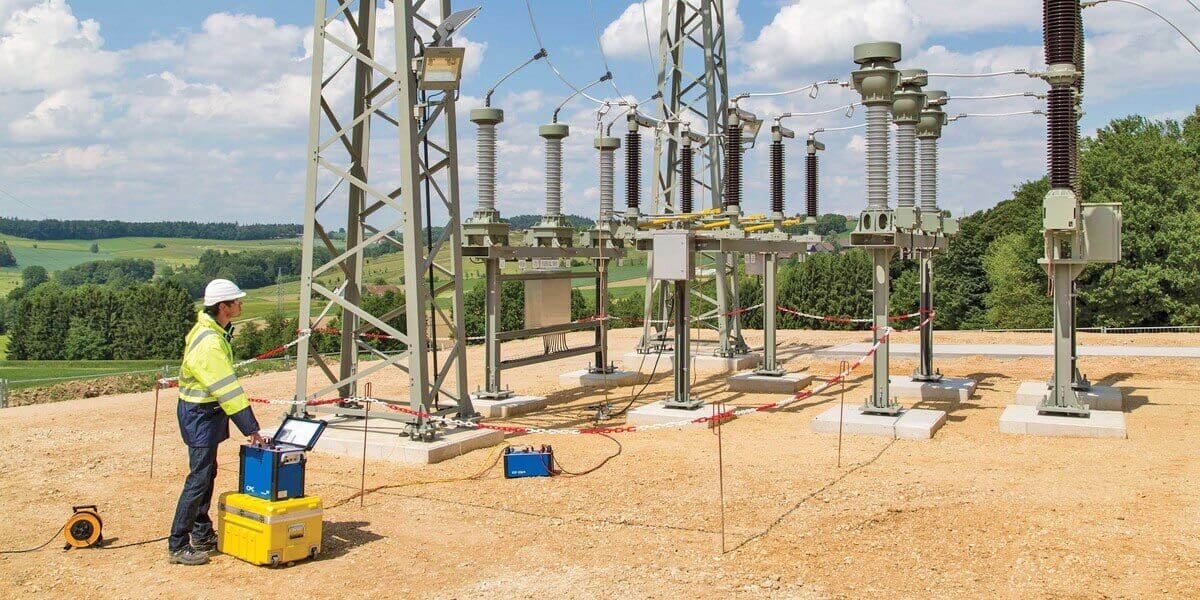
Figure 1 – Performing primary injection testing on-site
In the second part of this article, we’ll delve deeper into multi-core current transformers. These transformers feature both protection and metering cores, each serving distinct purposes. The protection core is responsible for overload protection, fault detection and clearing, and coordination with protective relays. It is designed to handle high currents and maintain accuracy even under high saturation conditions.
Conversely, the metering core facilitates accurate measurement of current, power quality monitoring, data logging, and recording. It operates at a low saturation point to ensure precise measurement in various conditions.
Additional considerations in the commissioning process include the role of the low voltage compartment and the CT loop in medium voltage switchgear. These components play a vital role in ensuring the safe and reliable operation of current transformers and their integration into switchgear systems.
Finally, we shall explore the concept of CT ratio, which represents the relationship between primary and secondary currents. Understanding CT ratios is really essential for accurate current measurement and coordination with protective relays.
Throughout this article, we aim to provide a comprehensive overview of primary injection testing and current transformer commissioning, providing engineers and professionals with the knowledge and understanding required to ensure accurate measurement and effective protection in electrical systems.
Also, I believe you can find my courses very useful in further studying this and many other topics related to power substations and relay protection.
- Introduction to primary injection testing
- Essential Terminology and key concepts for CTs Commissioning
- CT Terminal Box: Wiring Hub for CT Secondary Connections
- CT Junction Boxes or Dedicated CT Panels
- Local Control Cubicles (LCC) Panels: Centralized Control and Monitoring
- Comprehending the Current Transformer Loop and its Verification Procedure
- Polarity Marking in CTs: Ensuring Accurate Connection and Measurement
- Multi-Core Current Transformers
- Distinct Purposes: Protection Cores and Metering Cores in CTs
- Role of LV Compartment and CT Loop in MV Switchgear
- Understanding CT Ratio: The Relationship Between Primary and Secondary Currents
- Current Transformer Circuit Shorting and Grounding Facility
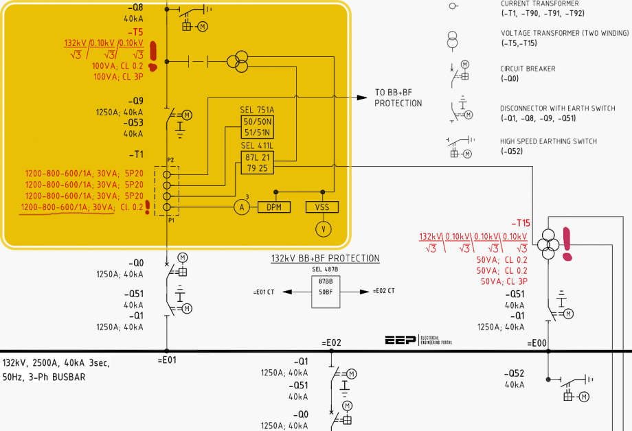
- BONUS! 13.8kV and 132kV Substation Single-Line Diagrams (PDF)
1. Introduction to Primary Injection Testing
Primary injection testing is a method used to verify the performance and functionality of protective devices, such as current transformers, relays, and trip units, by injecting a calibrated current directly into the primary side of the equipment. In electrical systems, the terms “primary side” and “secondary side” refer to different sections of a device or system based on their relative position in the power flow.
Here’s an explanation of these terms:
Primary Side of CT
The primary side of a device or system is where the input power is received or supplied. It is typically connected to the higher voltage or higher power side of the system. In the case of current transformers, the primary side is where the high-voltage power is delivered, and it is usually connected to the utility power source or the power generation system.
For example, in a current transformer used in medium voltage level, the primary side considered as the conductor, where power is being delivered, primary side of current transformer senses the current flowing in the conductor / busbar / line.
Figure 2 – Primary and the secondary sides of the HV current transformer
Secondary Side of CT
The secondary side of a device or system is where the output power is delivered or used. It is typically connected to the lower voltage or lower power side of the system. In the case of current transformers, the secondary side is where the stepped-down current is available.
At the CT secondary not only the current but also the voltage is reduced.
For example, if a current transformer primary is connected at 380kV system voltages and having a CT ratio of 2000/1 Amp, it indicates that if 2000 thousand amp is flowing through the CT primary then 1 amp will be available at the CT secondary side, furthermore voltage available at CT secondary will also be low voltages in order of few volts.
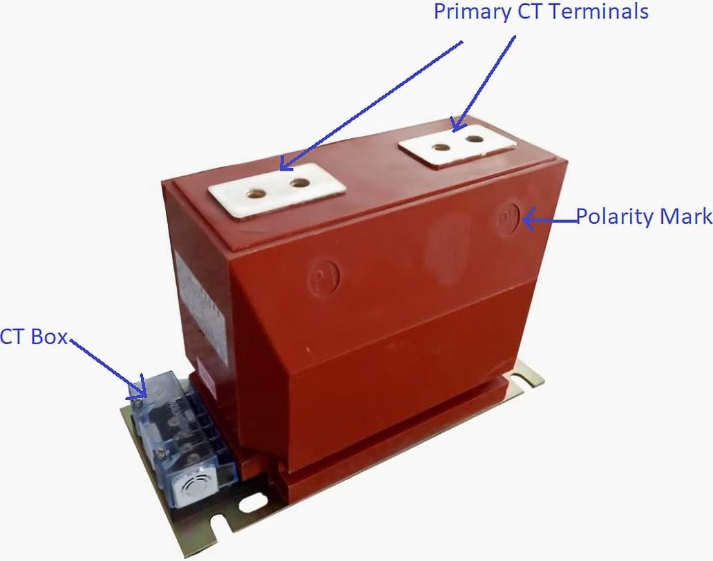
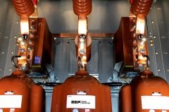
Figure 3 – Medium Voltage Current Transformer (CT)
Generally speaking, transformers are used to facilitate coupling whenever the voltage or current in a power circuit is too high to allow for the direct connection of measurement instruments or relays. These measuring transformers are essential for producing a scaled-down duplicate of the input quantity to the necessary level of precision for the specific measurement.
Figure 4 – Basic representation of the current transformer primary and secondary sides

Go back to the Contents Table ↑
2. Terminology and Key Concepts
(Essential For Current Transformers Commissioning)
To comprehend the commissioning of current transformers, it is vital for protection engineers to familiarize themselves with specific terminologies employed during primary injection testing. These terminologies hold significance in grasping the fundamental concepts related to current transformer operation and evaluation.
Having covered the primary and secondary sides of current transformers, let’s now dive into a deeper understanding of the following aspects:
Related electrical guides & articles


Muhammad Kashif
Muhammad Kashif Shamshad is an Electrical Engineer and has more than 17 years of experience in operation & maintenance, erection, testing project management, consultancy, supervision, and commissioning of Power Plant, GIS, and AIS high voltage substations ranging up to 500 kV HVAC & ±660kV HVDC more than ten years experience is with Siemens Saudi Arabia.Profile: Muhammad Kashif
