
Estimated Study Time: 11 minutes
Why Primary Injection Tests?
This type of test involves the entire circuit – current transformer primary and secondary windings, relay coils, trip and alarm circuits, and all intervening wiring are checked. There is no need to disturb wiring, which obviates the hazard of open-circuiting current transformers, and there is generally no need for any switching in the current transformer or relay circuits.
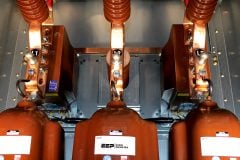
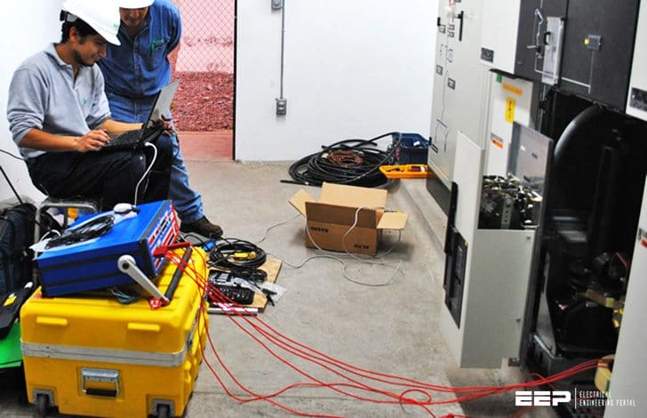 Primary Injection Testing Of Protection System For Wiring Errors Between VTs / CTs and Relays (photo credit: Varitel Proyectos e Ingeniería SAS)
The drawback of such tests is that they are time consuming and expensive to organize.
Increasingly, reliance is placed on all wiring and installation diagrams being correct and the installation being carried out as per drawings, and secondary injection testing being completed satisfactorily. Under these circumstances, the primary injection tests may be omitted.
This hazard is much reduced where digital/numerical relays are used, since the current and voltage measurement/display facilities that exist in such relays enable checking of relay input values against those from other proven sources. Many connection/wiring errors can be found in this way, and by isolating temporarily the relay trip outputs, unwanted trips can be avoided.
Primary injection testing is, however, the only way to prove correct installation and operation of the whole of a protection scheme.
Primary injection tests are always carried out after secondary injection tests, to ensure that problems are limited to the VTs and CTs involved, plus associated wiring, all other equipment in the protection scheme having been proven satisfactory from the secondary injection tests.
1. Test Facilities
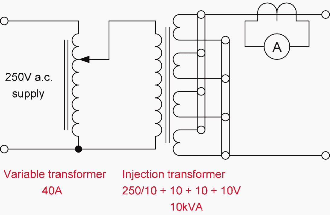
An alternator is the most useful source of power for providing the heavy current necessary for primary injection. Unfortunately, it is rarely available, since it requires not only a spare alternator, but also spare busbars capable of being connected to the alternator and circuit under test.
These can be connected in series or parallel according to the current required and the resistance of the primary circuit. Outputs of 10V and 1000A can be obtained.
Alternatively, modern PC-controlled test sets have power amplifiers capable of injecting currents up to about 200A for a single unit, with higher current ratings being possible by using multiple units in parallel.
If the main current transformers are fitted with test windings, these can be used for primary injection instead of the primary winding. The current required for primary injection is then greatly reduced and can usually be obtained using secondary injection test equipment.
Unfortunately, test windings are not often provided, because of space limitations in the main current transformer housings or the cost of the windings.
2. CT Ratio Check
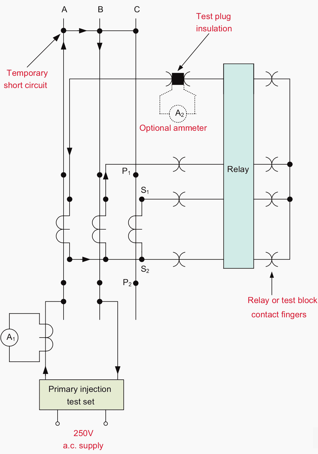
Current is passed through the primary conductors and measured on the test set ammeter, A1 in Figure 2. The secondary current is measured on the ammeter A2 or relay display, and the ratio of the value on A1 to that on A2 should closely approximate to the ratio marked on the current transformer nameplate.
3. CT Polarity Check
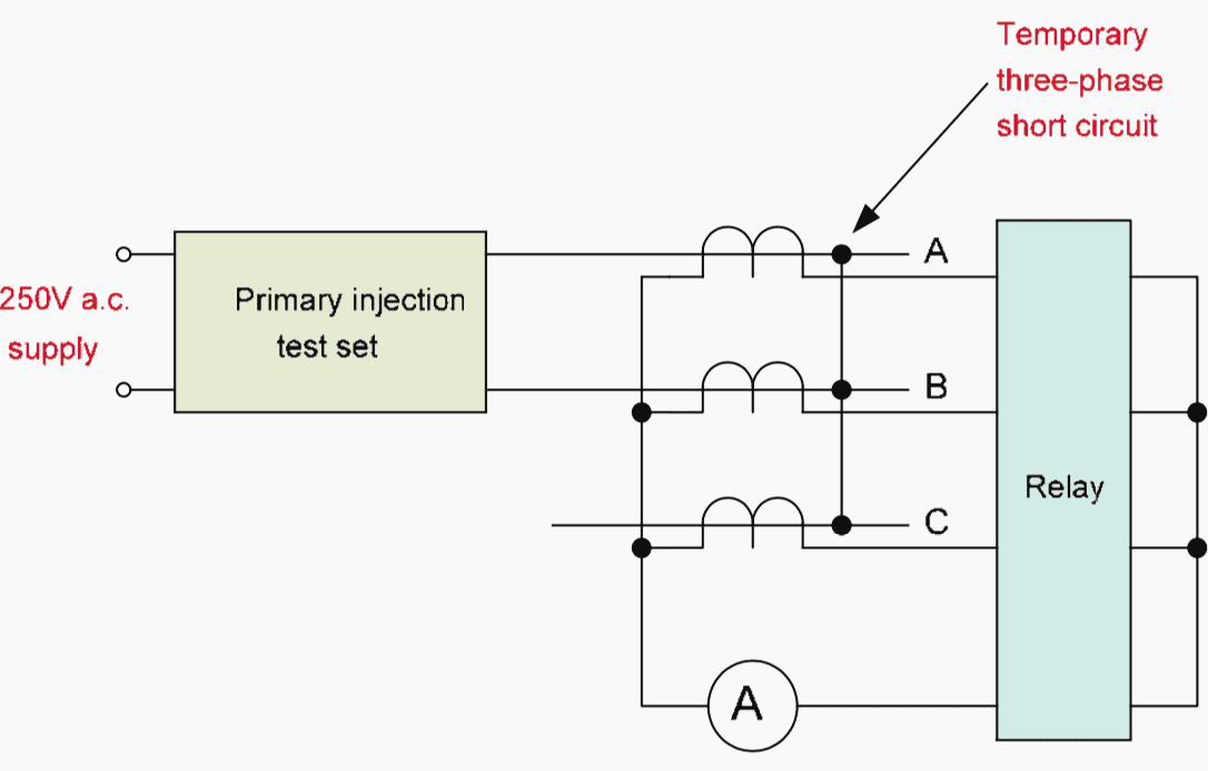
If the equipment includes directional, differential or earth fault relays, the polarity of the main current transformers must be checked. It is not necessary to conduct the test if only overcurrent relays are used.
The circuit for checking the polarity with a single-phase test set is shown in Figure 3. A short circuit is placed across the phases of the primary circuit on one side of the current transformers while single-phase injection is carried out on the other side.
If an electromechanical earth-fault relay with a low setting is also connected in the residual circuit, it is advisable to temporarily short-circuit its operating coil during the test, to prevent possible overheating. The single-phase injection should be carried out for each pair of phases.
4. Primary Injection Testing of Relay Elements
As with secondary injection testing, the tests to be carried out will be those specified by the client, and/or those detailed in the relay commissioning manual.
Testing Of Protection Scheme Logic
Testing the logic of protection schemes is obligatory part in testing and commissioning process. Protection schemes often involve the use of logic to determine the conditions under which designated circuit breakers should be tripped.
Traditionally, this logic was implemented by means of discrete relays, separate from the relays used for protection. Such implementations would occur where electromechanical or static relay technology is used. However, digital and numerical relays normally include programmable logic as part of the software within the relay, together with associated digital I/O.
Changes to the logic are carried out using software hosted on a PC (or similar computer) and downloaded to the relay. Use of languages defined in IEC 61131, such as ladder logic or Boolean algebra is common for such software, and is readily understood by Protection Engineers.
Further, there are several commonly encountered protection functions that manufacturers may supply with relays as one or more ‘default’ logic schemes.
Because software is used, it is essential to carefully test the logic during commissioning to ensure correct operation. The only exception to this may be if the relevant ‘default’ scheme is used. Such logic schemes will have been proven during relay type testing, and so there is no need for proving tests during commissioning.
A specific test procedure should be prepared, and this procedure should include:
- Checking of the scheme logic specification and diagrams to ensure that the objectives of the logic are achieved
- Testing of the logic to ensure that the functionality of the scheme is proven
- Testing of the logic, as required, to ensure that no output occurs for the relevant input signal combinations
The degree of testing of the logic will largely depend on the criticality of the application and complexity of the logic. The responsibility for ensuring that a suitable test procedure is produced for logic schemes other than the ‘default’ one(s) supplied lies with the specifier of the logic.
IMPORTANT! Relay manufacturers cannot be expected to take responsibility for the correct operation of logic schemes that they have not designed and supplied.
Tripping And Alarm Annunciation Tests
If primary and/or secondary injection tests are not carried out, the tripping and alarm circuits will not have been checked. Even where such checks have been carried out, CB trip coils and/or Control Room alarm circuits may have been isolated.
In such cases, it is essential that all of the tripping and alarm circuits are checked. This is done by closing the protection relay contacts manually and checking that:
- The correct circuit breakers are tripped x the alarm circuits are energized
- The correct flag indications are given
- There is no maloperation of other apparatus that may be connected to the same master trip relay or circuit breaker
Many designs of withdrawable circuit breaker can be operated while in the maintenance position, so that substation operation can continue unaffected except for the circuit controlled by the circuit breaker involved. In other cases, isolators can be used to avoid the need for busbar de-energisation if the circuit involved is not ready for energisation.
Reference // Network Protection & Automation Guide by Alstom
Related electrical guides & articles


Edvard Csanyi
Hi, I'm an electrical engineer, programmer and founder of EEP - Electrical Engineering Portal. I worked twelve years at Schneider Electric in the position of technical support for low- and medium-voltage projects and the design of busbar trunking systems.I'm highly specialized in the design of LV/MV switchgear and low-voltage, high-power busbar trunking (<6300A) in substations, commercial buildings and industry facilities. I'm also a professional in AutoCAD programming.
Profile: Edvard Csanyi

Hi,
To test IDMTL Relays, can i use PI Test set?
I am interested in primary and secondary switchgear testing that my company is asking to be performed.
Powerful place to learn about electric
Wanting to get more insight on electrical
Good work done
I am a lot of interest in AC motor protection
I miss so much this kind of job. i began my career testing relays. it was fun, and i learned a lot!
Dear how are you.
I am interested in learning the relays testing.
It’s my second 132/22kv project and I want the relays testing and commissioning..
Would you help me plz..
It’s my WhatsApp number
00923027945665