
Estimated Study Time: 15 minutes
Primary distribution systems
Primary distribution systems consist of feeders that deliver power from distribution substations to distribution transformers. A feeder usually begins with a feeder breaker at the distribution substation. Many feeders leave substation in a concrete ducts and are routed to a nearby pole. At this point, underground cable transitions to an overhead three-phase main trunk.
 Primary and secondary power distribution systems (layouts explained)
The main trunk is routed around the feeder service territory and may be connected to other feeders through normally-open tie points. Underground main trunks are possible-even common in urban areas, but cost much more than overhead construction.
Lateral taps off of the main trunk are used to cover most of a feeder’s service territory. These taps are typically single phase, but may also be two phases or three phases.
Overhead laterals use pole-mounted distribution transformers to serve customers and underground laterals use pad mount transformers. Feeder routes must pass near every customer. To accomplish this, each substation uses multiple feeders to cover an allocated service territory.
An illustrative feeder showing different types of laterals and devices is shown in Figure 1.
The simplest primary distribution system consists of independent feeders with each customer connected to a single feeder. Since there are no feeder interconnections, a fault will interrupt all downstream customers until it is repaired.
A slightly more common configuration connects two feeders together at their endpoints with a normally open tie switch. This primary loop increases reliability by allowing customers downstream of a fault to receive power by opening an upstream switch and closing the tie switch. The only customers that cannot be restored are those in switchable section where the fault occurred.
Many distribution systems have multiple tie switches between multiple feeders. Reliability benefits are similar to a primary loop with greater switching flexibility.
These highly interconnected primary distribution systems are referred to as radially operated networks.
Certain classes of customers require higher reliability than a single feeder can provide.
Primary selective service connects each customer to a preferred feeder and an alternate feeder. If the preferred feeder becomes de-energized, a transfer switch disconnects the preferred feeder and connects the alternate feeder.
Secondary selective service achieves similar results by using switches on secondary voltages rather than primary voltages. With secondary selective service, each distribution transformer must be able to supply the entire load for maximum reliability benefits.
They are common in central business districts and high-density areas and are being applied frequently in outlying areas for large commercial services where multiple supply feeders can be made available.
Some typical primary distribution system configurations are shown in Figure 2.
A spot network typically comprises a secondary network that serves a singular, concentrated load, such as a high-rise building or shopping mall, necessitating a high level of reliability. The secondary spot network bus is concurrently fed by two or more primary feeders via network transformers.
A spot network load of up to 25 MVA may be supplied by as many as six primary feeds. Nearly all spot networks in North America function at a 480Y/277-V secondary voltage.
High service dependability and operational flexibility are attained with a spot network supplied by two or more primary feeds via network transformers. The secondary bus is perpetually powered by all network transformers.
Secondary distribution systems
A low-voltage network or secondary network is a part of electric power distribution which carries electric energy from distribution transformers to electricity meters of end customers.
Secondary networks are operated at a low voltage level, which is typically equal to the mains voltage of electric appliances. Most modern secondary networks are operated at AC rated voltage of 100–120 or 230–240 volts, at the frequency of 50 or 60 hertz.
Operating voltage, required number of phases (three-phase or single-phase) and required reliability dictate topology and configuration of the network.
Electric power distribution systems are designed to serve their customers with reliable and high-quality power. The most common distribution system consists of simple radial circuits (feeders) that can be overhead, underground, or a combination.
Distribution transformers or secondary transformers, placed along feeders, convert the voltage from the medium to a low voltage level, suitable for direct consumption by end customers (mains voltage).
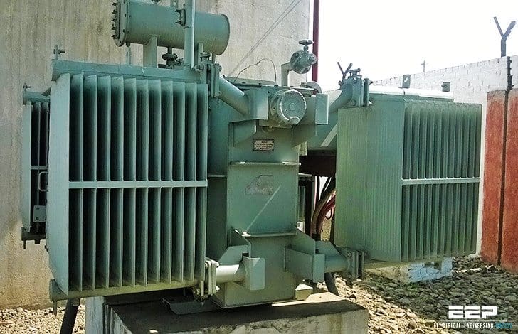
Typically, a rural primary feeder supplies up to 50 distribution transformers, spread over a wide region but the figure significantly varies depending on configuration. They are sited on pole tops, cellars or designated small plots.
From these transformers, low voltage or secondary network branches off to the customer connections at customer premises, equipped with electricity meters.
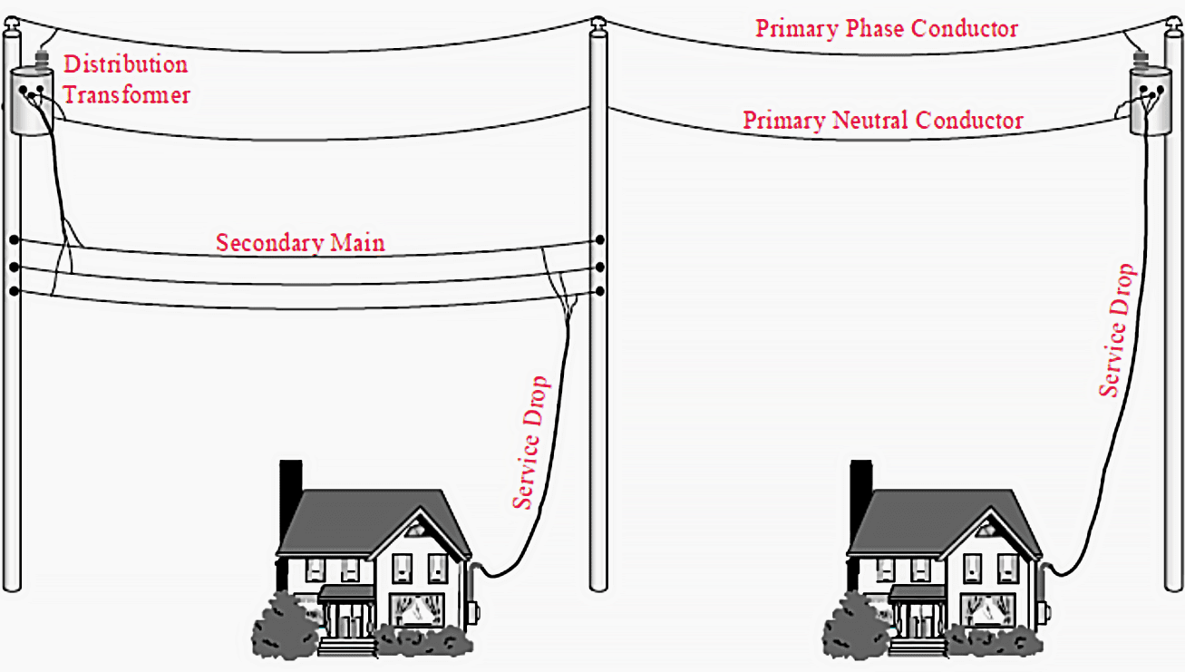
Customers are connected to distribution systems via service drops. Customers close to a distribution transformer are able to have service drops directly connected to transformer secondary connections. Other customers are reached by routing a secondary main for service drop connections.
These two types of service connections are shown in Figure 3 above.
Systems utilizing secondary mains are characterized by a small number of large distribution transformers rather than a large number of small distribution transformers
Many underground systems connect service drops directly to distribution transformers and do not use secondary mains. This forces distribution transformers to be located within several hundred feet of each customer, but eliminates the reliability concerns associated with T-splices that are required to connect underground service drops to underground secondary mains.
Configuration of secondary distribution systems
Radial networks
Radial operation is the most widespread and most economic design of both MV and LV networks. It provides a sufficiently high degree of reliability and service continuity for most customers. In American (120 V) systems, the customers are commonly supplied directly from the distribution transformers via relatively short service drop lines, in star-like topology.
In 240 V systems, the customers are served by several low-voltage feeders, realized by overhead power lines, aerial or underground power cables, or their mixture.
In an overhead network, service drops are drawn from pole tops to roof connections. In a cable network, all necessary connections and protection devices are typically placed in pad-mounted cabinets or, occasionally, manholes (buried T-joint connections are prone to failures).
Rural areas with low-density loads are usually served by overhead primary lines that are mounted on poles and contain distribution transformers, fuses, switches, and other equipment. Subterranean cable systems equipped with distribution transformers and switchgear, situated in underground vaults or ground-level cabinets, cater to high-density loads in metropolitan environments.
Power-system protection in radial networks is simple to design and implement, since short-circuit currents have only one possible path that needs to be interrupted.
Fuses are most commonly used for both short-circuit and overload protection, while low-voltage circuit breakers may be used in special circumstances.
Spot networks
Spot networks are used when increased reliability of supply is required for important customers. The low-voltage network is supplied from two or more distribution transformers at a single site, each fed from a different MV feeder (which may originate from the same or different substations).
The transformers are connected together with a bus or a cable on secondary side, termed paralleling bus or collector bus. The paralleling bus typically does not have connecting cables (reaches) to other network units, in which case such networks are termed isolating spot networks. When they have, they are referred to as spot networks with reach.
In some cases, fast-acting secondary bus tie breakers may be applied between bus sections to isolate faults in the secondary switchgear and limit loss of service.
In normal operation, the energy supply is provided by both primary feeders in parallel. In case of an outage of either primary feeder, network protector device at the corresponding spot transformer secondary automatically opens. The remaining transformers continue to provide supply through their respective primary feeders.
Only in cases when the short circuit is located at the paralleling bus, or a total loss of primary supply occurs, the customer will remain out of service. Faults on the low-voltage network are handled by fuses or local circuit breakers, resulting in loss of service only for the affected loads.
Grid networks
A grid networks consist of an interconnected grid of circuits, energized from several primary feeders through distribution transformers at multiple locations. Grid networks are typically featured in downtowns of large cities, with connecting cables laid out in underground conduits along the streets.
Numerous cables allow for multiple current paths from every transformer to every load within the grid.
Individual cable sections may be protected by cable limiters on both ends, special fuses providing very fast short-circuit protection.
The inherent system redundancy generally prevents any customer from experiencing outage.
References:
- Risk Analysis in Low Voltage, Secondary, Power Distribution System by Mostafa Aliyari
- Electric Distribution Systems by Abdelhay A. Sallam and Om P. Malik
- Electric Power Distribution Handbook by Short, T.A.
Related electrical guides & articles


Edvard Csanyi
Hi, I'm an electrical engineer, programmer and founder of EEP - Electrical Engineering Portal. I worked twelve years at Schneider Electric in the position of technical support for low- and medium-voltage projects and the design of busbar trunking systems.I'm highly specialized in the design of LV/MV switchgear and low-voltage, high-power busbar trunking (<6300A) in substations, commercial buildings and industry facilities. I'm also a professional in AutoCAD programming.
Profile: Edvard Csanyi

am interested in commercial and industrial electrical ,also electrical distribution ,i wanna be a contractor i think your portal can be helpful
god description as a starter to dig deeper, thank you.How to calculate a voltage drop at the customer switchbord for network grid. Do we even need to worry about the voltage drop in the network? I think that any voltage drop should be calculated from a node, or bus where the services are connected to, not from the transformer and the secondary mains (main secondary cables from the transformer to the node/bus). Am I right?
Nice to meet you enger
Dear Engr. Edvard Csanyi
Thank you very much. I learned a lot from your calculation especially on EXCEL calculation. I also forward your link to my friend who also can learnt from you.
Thank you very much.
Dear Engr. Edvard,
After reading through your article i realized that i may discovered the solution for a long distribution problem in my country, i will prefer to place a call to you directly so that i can explain in details through phone call, please i will be delight if i can get your mobile number for further briefing.
thanks.
Michael Omodara.
Hello Eng Edvard,
Am an Engineer as well and am looking for LV distribution system articles/guides for rural areas..
Any leads can help
Rgds,
Brian
Dear Engr. Edvard Csanyi,
Thank you so much for always sending me your post about electrical engineering. These things helped me a lot.
Keeping in-touch all the time.
Engr. Ellezer G. Casiño
Edvard , Thanks for this article , I have question for you , what is the typical turn around time in the industry designing a four story office building 70,000 SF , a TJ Maxx store or 10 story , 80 unit Hotel
What are the rules of thumb , do you have a way to go by square foot for let us say for residential , commercial , or industrial buildings roughly?
I used to work for a PE sporadically , but now I thinking about going corporate..
Thank you in addvance.